
 Business License

The advantages and disadvantages of the installation method of American standard current transformer
Is 600 V through core CT commonly used in metal armored switchgear? Core CT has a lower cost than high-pressure epoxy pillar CT, providing users with more economical products
The through core CT does not include the primary conductor as a component of the CT itself, thereby isolating the CT from the main dielectric and thermal stress. The impact of CT heating is relatively small, and the heating of the primary conductor is directly emitted into the air instead of epoxy resin, which does not increase the risk of CT overheating and aging.
The primary conductor support for short-circuit electric power is provided by the switchgear structure and circuit breaker primary conductor, rather than by CT, which allows for higher short-circuit levels. CT itself does not need to withstand dynamic and thermal stability, and epoxy pillar CT often cannot meet the requirements of dynamic and thermal stability for small transformation ratios. Due to the fact that CTs are not directly located in the high-voltage bus structure, they are easier to maintain, inspect, replace (for example, if ratio changes are required), or add CTs after initial installation. Through hole CTs are easily available in variable ratio configurations. As for PX level, CT with different transformation ratios can be installed on a casing to form different protection functions. The delivery time for through the core CT is usually shorter than that for high-voltage CT. The use of a through core CT allows for the installation of the CT in the circuit breaker compartment, surrounding the main disconnect component, thereby saving space in the busbar compartment and cable compartment. Two CTs can be installed on each phase, and four current transformers can be installed on the upper and lower contact boxes of one circuit breaker. Especially for busbar side current transformers that require differential protection, epoxy pillar type transformers require a large installation space and generate significant heat, directly causing the temperature rise in the busbar room to exceed the standard. The effect of high current transformers is more obvious. The through type current transformer does not require a thick primary conductor to be cast inside the epoxy resin, reducing the overlap resistance of copper bars in the incoming and outgoing line connections and minimizing heat generation. Using a tubular busbar to directly pass through, with high conductivity and good heat dissipation.
So what are the shortcomings or drawbacks?
Firstly, the insulation issue needs to be addressed. Unlike medium voltage bushing current transformers, 600V through type current transformers meet the requirements for medium voltage insulation. The 600V current transformer has a power frequency withstand voltage of 3kV and a lightning impulse withstand voltage of 10kV. Therefore, contact boxes or insulated conductive rods are required to meet the insulation performance requirements. For 15kV, internal and external voltage equalization shielding is generally not required. For 27/38kV, the contact box must use internal and external shielding to meet insulation requirements.
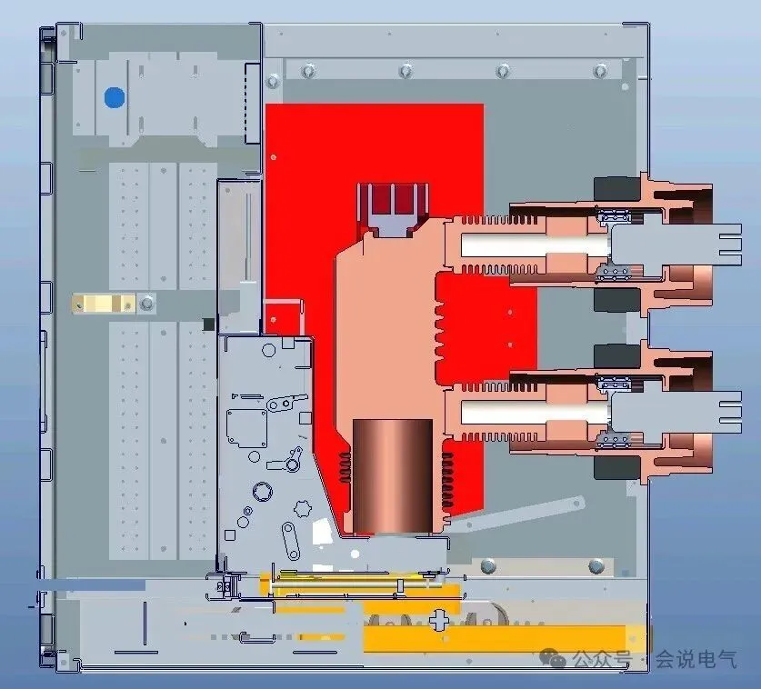
Secondly, when the ratio is small, the size is larger or the capacity is relatively small. If the capacity of 75:5 and 5P20 can only reach 2.5VA and the measurement accuracy can only reach 4.8, it can meet the requirements in the use of American standard switchgear. However, it cannot meet the requirements for high-precision and capacity demanding scenarios. For electricity metering and other purposes, this type of through type current transformer cannot be used.
Another issue is that installing CT leads to an increase in the depth of the circuit breaker compartment. To install a current transformer on the contact box, a front end contact box is required. This increases the depth of the entire circuit breaker compartment.
For safety reasons, CT replacement needs to be carried out with the valve open. At this time, the power must be cut off before the valve can be opened. If the power is not cut off, it will directly expose the operator to high-voltage charged bodies, which is very dangerous.
Current transformers can also be installed behind cabinets, insulated and supported by insulating sleeves or insulating conductive rods, and can also be used for transformer applications. For current transformers with larger inner diameters, circular conductors with small-diameter heat shrinkable sleeves can be used without insulation sleeves, as long as the air gap is large enough to meet insulation requirements.
Recently Posted
-
Jinhua Dika Electrical Equipment: Manufacturing Transformers and Switchgear in Zhejiang, China
August 31, 2026When a buyer starts looking for a transformer or a complete switchgear set, the hardest part is often not the specification. It is Read More
 -
Environmentally friendly gas insulated 40.5kV switchgear
August 31, 2026There are two types of 40.5kV environmentally friendly gas insulated switchgear: one is used for ring network power supply, with l Read More
 -
The use of heat shrink tubing
August 31, 2026For the use of heat shrink tubing, foreign customers accept it as an insulation medium. According to the requirements of RAYCHEM 2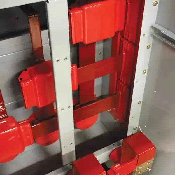 Read More
 -
American standard 38kV metal armored outdoor switchgear
August 31, 2026The power frequency withstand voltage of the 38kV switchgear is 80kV, and the lightning impulse withstand voltage is 150kV. For me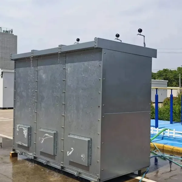 Read More

Contact Us
Recommended Products
-
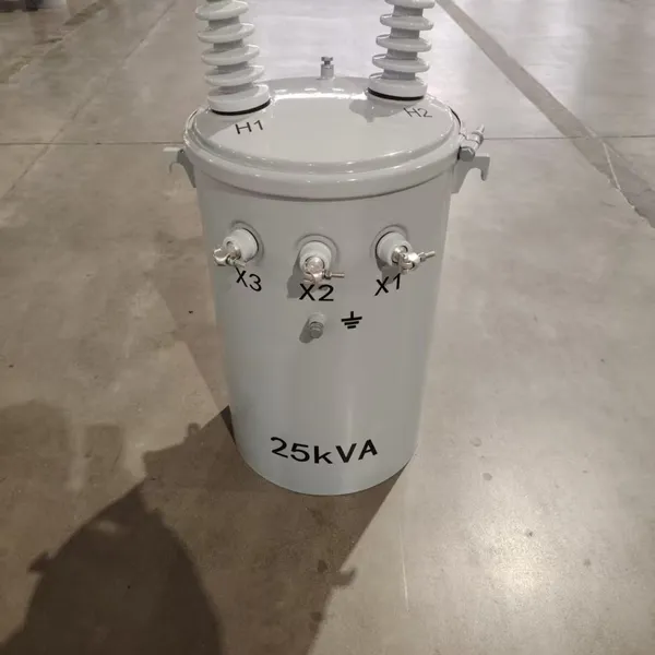
 Single Phase Oil Immersed Transformer 10KVA 15KVA 25KVA 37.5KVA Standard CompliantNegotiableMOQ: 2 Units
 -
Electrical Arc Furnace Transformers up to 120MVA - Certified for Steel Industry ApplicationsUS$ 8000 - 10000MOQ: 1 Unit
-
3-Phase Oil Type Transformer 5-Year Warranty With Load Test ReportUS$ 5428 - 5628MOQ: 1 Unit
-
Three Phase Oil Filled Transformer for Mining Operations Dust-Proof DesignUS$ 5428 - 5628MOQ: 1 Unit
-
HV Three Phase Oil Filled Transformer With ONAN Cooling 500kVA-2500kVAUS$ 5428 - 5628MOQ: 1 Unit
-
11/24/33KV High Voltage Isolation Switch With Mill Test ReportUS$ 800MOQ: 1 Unit
-
3-Pole Outdoor Isolation Switch With 5-Year Warranty and Compliance TestingUS$ 800MOQ: 1 Unit
-
YH5WZ 3KV-110KV Zinc Oxide Arrester for Power Station Outdoor High Voltage DistributionUS$ 21MOQ: 100 Units
-
Outdoor SF6 Load Break Switch LW30-72.5/1250A 24KV 630A 16KA Three PhaseUS$ 10000MOQ: 1 Unit
-
Input Line Reactor for CNC Machine Frequency Converters, 400V 60HzUS$ 65MOQ: 5 Units
-
Industrial Grade 35-220KV Oil-Immersed Current Transformer for SubstationsUS$ 480 - 500MOQ: 3 Units
-
LZZBJ9-20 Indoor 24kV High Voltage Cabinet Single-Phase 5-20 for Industrial Power SystemsUS$ 250MOQ: 3 Units
-
17.5 KV Full-enclosed Outdoor Epoxy Resin Casting and Double Pole Insulated Voltage TransformerUS$ 90 - 100MOQ: 1 Piece
-
Three Phase 30kVA SVC Voltage Regulator for Textile Manufacturing, Stable OutputUS$ 159MOQ: 10 Units
-
Amorphous Core 25kVA Transformer Compliant With IEC Standards for Power DistributionUS$ 1300 - 2900MOQ: 2 Units
-
CHINT NM8NDC-630 DC 1000V/Ui High-Voltage Circuit Breaker With 630A Frame CurrentUS$ 425 - 625MOQ: 100 Units
-
High Voltage Drop Out Fuse Cutout 33KV 27KV 24KV for Overhead LinesUS$ 35MOQ: 100 Units
-
TVR-10 KVA Automatic Voltage Stabilizer 220V ±0.5% Accuracy for Laboratory InstrumentsUS$ 103 - 123MOQ: 1 Unit
-
Universal 5000VA Voltage Transformer for International Appliances 110V-220VUS$ 102 - 107MOQ: 10 Units
-
500kV Three-Phase Oil-Immersed Auto Transformer 250MVA for Power GridsUS$ 800 - 9000MOQ: 1 Unit