
North American low-voltage switchgear
There are two main types of low-voltage switchgear in North America. One is power switchgear, with the standard IEEE C37.20.1/UL1558, which belongs to primary distribution cabinets. The other is UL891 low-voltage distribution panel, which is a switchgear used on the user side.
The low-voltage distribution panel SWITCHBOARD reference standard UL891 has different types of access, such as front entry and rear entry. The DEAD FRONT COVER is fixedly installed in the form of a front cover plate, with a frame circuit breaker as the incoming line isolation and a molded case circuit breaker as the outgoing line. It can be a fixed or quick plug structure. The incoming cable can be connected in front of the cabinet or behind the cabinet, and the plastic shell outgoing cable can be connected on the front side.
Distribution panel standard:
■ ANSI C37.13, C37.16, C37.17,ANSI C37.50; ANSI/NEMA PB 2
■UL-891, CUL C22.2
The low-voltage side of transformers in North American projects generally uses Switcboard distribution panels, with the standard term Dead front Switcboard, which means that the front panel of the distribution panel is fixed and sealed, leaving only circuit breaker operation holes, such as the panel of the frame circuit breaker and the operating handle for moving and opening the molded case circuit breaker up and down. The frame circuit breaker can be manually or electrically operated, while the molded case circuit breaker can be manually opened and closed.
The maximum current of the distribution panel can reach 6000A, and the short-circuit breaking of the switch can reach 100kA. Unlike the switchgear, the installation density of the distribution panel is high, simple and efficient. The distribution panel does not require excessive protection level, internal arc level, short-term withstand current, compartment separation between functional units, excessive secondary control protection, complex operating mechanism, or rocking in and out. This structure ensures temperature rise under high installation density, facilitates and simplifies cable connections, simplifies maintenance operations, and greatly improves reliability.
The North American standard UL891 distribution panel has its unique design requirements, and the standard clearly defines the structural requirements. The horizontal busbar is located in the middle of the rear of the cabinet, generally in two groups, with a maximum current of 6000A and 150kA.
Especially for the outgoing lines of molded case circuit breakers, they must be installed horizontally and arranged in groups of Group Type. The quantity and capacity of the outgoing lines on both sides or one side are defined.
The current specification of the vertical busbar of the molded case circuit breaker output cabinet should adopt a dispersion factor according to the number of installed circuits, and also consider the current requirements for the expansion of the empty module space. According to the design, 16 250A molded case circuit breakers can be installed for output. If only 8 250A molded case circuit breakers are installed, the dispersion factor of the 8 molded cases may be 0.6, and the total current is 250 * 8 * 0.6=1200A. However, since only 8 modules are installed and there are still 8 empty molded case modules, according to the standard, a coefficient of 1.6 needs to be reserved, so the vertical busbar needs 1200 * 1.6=1920A.
The output current of UL891 molded case circuit breaker can reach 1200A, and one distribution panel can install four 1200A molded case circuit breakers as output circuits.
The UL891 distribution panel generally uses copper bars to directly fix the vertical busbar and the incoming end of the molded case circuit breaker. The outgoing side of the molded case circuit breaker is equipped with cable ends, that is, the stripped copper core of the cable can be directly inserted into the outgoing cable end of the molded case circuit breaker for connection. For high current, each phase can connect 4 300 square cables.
For incoming cabinets and bus tie cabinets, fixed frame circuit breakers are generally used. DEAD FRONT means that the front is completely fixed and generally not allowed to be opened, so using withdrawable circuit breakers is also meaningless.
The incoming cabinet is directly connected to the transformer box and reaches the horizontal busbar through the incoming circuit breaker. The outgoing line of the frame circuit breaker is connected by cables or connected to the load center through a dense busbar bridge, which is connected to the local distribution box Panelboard.
Recently Posted
-
System scheme and primary structure of American standard medium and low voltage switchgear
July 1, 2026The system scheme for power distribution comprehensively reflects the direction of power flow, current distribution, short-circuit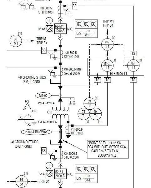 Read More
 -
IEC 17.5kV switchgear Guzhou Weng will speak on electrical June 28, 2026 05:03 2 people
June 30, 202617.5kV is the IEC standard voltage level, applied in power systems with voltages of 13.2/13.8/15kV. IEC 17.5kV metal enclosed swit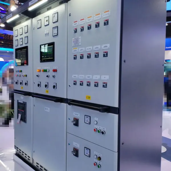 Read More
 -
Design points of customized switchgear
June 30, 2026With the increasing demand for new energy and data centers, in addition to standardized products, there is a need for a large numb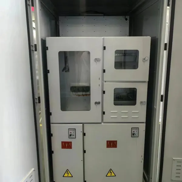 Read More
 -
Marine low-voltage switchgear
June 30, 2026Marine low-voltage switchgear needs to meet the special requirements of ship application systems, environments, etc., and develop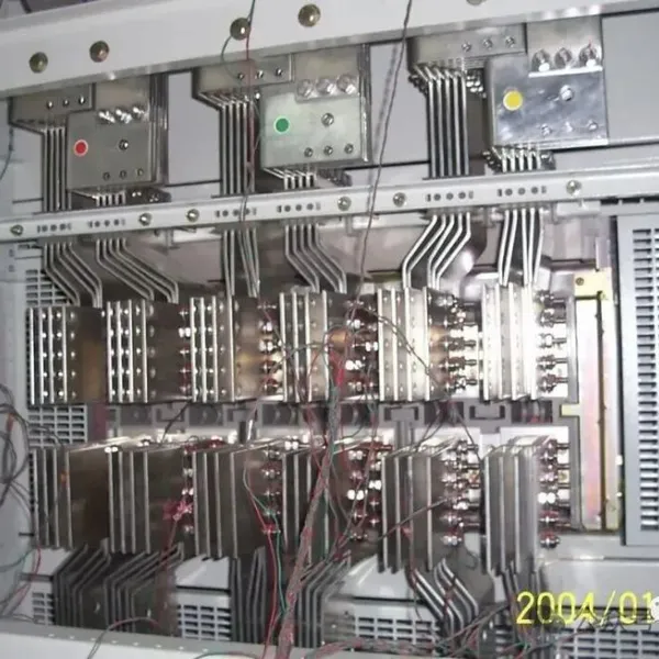 Read More

Contact Us
Recommended Products
-
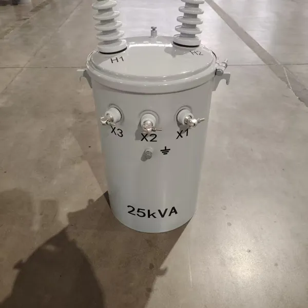
 Single Phase Oil Immersed Transformer 10KVA 15KVA 25KVA 37.5KVA Standard CompliantNegotiableMOQ: 2 Units
 -
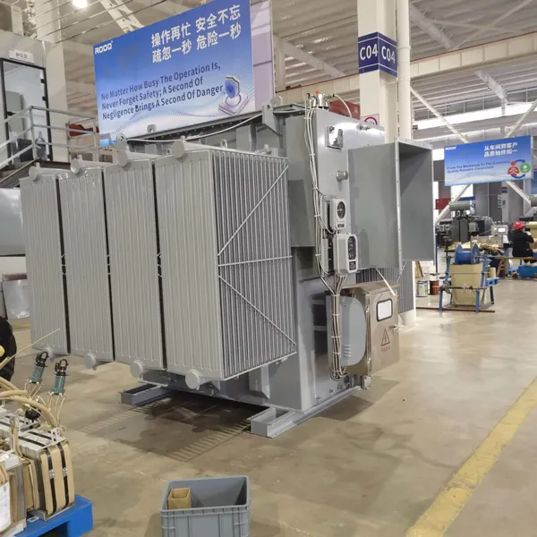
Electrical Arc Furnace Transformers up to 120MVA - Certified for Steel Industry ApplicationsUS$ 8000 - 10000MOQ: 1 Unit
-
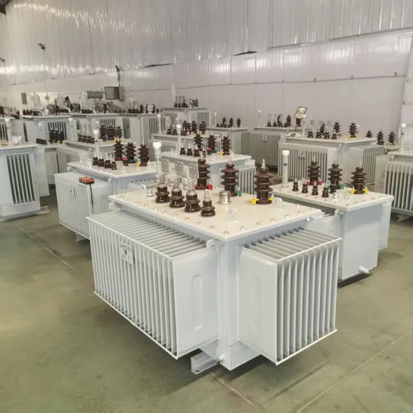
3-Phase Oil Type Transformer 5-Year Warranty With Load Test ReportUS$ 5428 - 5628MOQ: 1 Unit
-
Three Phase Oil Filled Transformer for Mining Operations Dust-Proof DesignUS$ 5428 - 5628MOQ: 1 Unit
-
HV Three Phase Oil Filled Transformer With ONAN Cooling 500kVA-2500kVAUS$ 5428 - 5628MOQ: 1 Unit
-
11/24/33KV High Voltage Isolation Switch With Mill Test ReportUS$ 800MOQ: 1 Unit
-
3-Pole Outdoor Isolation Switch With 5-Year Warranty and Compliance TestingUS$ 800MOQ: 1 Unit
-
YH5WZ 3KV-110KV Zinc Oxide Arrester for Power Station Outdoor High Voltage DistributionUS$ 21MOQ: 100 Units
-
Outdoor SF6 Load Break Switch LW30-72.5/1250A 24KV 630A 16KA Three PhaseUS$ 10000MOQ: 1 Unit
-
Input Line Reactor for CNC Machine Frequency Converters, 400V 60HzUS$ 65MOQ: 5 Units
-
Industrial Grade 35-220KV Oil-Immersed Current Transformer for SubstationsUS$ 480 - 500MOQ: 3 Units
-
LZZBJ9-20 Indoor 24kV High Voltage Cabinet Single-Phase 5-20 for Industrial Power SystemsUS$ 250MOQ: 3 Units
-
17.5 KV Full-enclosed Outdoor Epoxy Resin Casting and Double Pole Insulated Voltage TransformerUS$ 90 - 100MOQ: 1 Piece
-
Three Phase 30kVA SVC Voltage Regulator for Textile Manufacturing, Stable OutputUS$ 159MOQ: 10 Units
-
Amorphous Core 25kVA Transformer Compliant With IEC Standards for Power DistributionUS$ 1300 - 2900MOQ: 2 Units
-
CHINT NM8NDC-630 DC 1000V/Ui High-Voltage Circuit Breaker With 630A Frame CurrentUS$ 425 - 625MOQ: 100 Units
-
High Voltage Drop Out Fuse Cutout 33KV 27KV 24KV for Overhead LinesUS$ 35MOQ: 100 Units
-
TVR-10 KVA Automatic Voltage Stabilizer 220V ±0.5% Accuracy for Laboratory InstrumentsUS$ 103 - 123MOQ: 1 Unit
-
Universal 5000VA Voltage Transformer for International Appliances 110V-220VUS$ 102 - 107MOQ: 10 Units
-
500kV Three-Phase Oil-Immersed Auto Transformer 250MVA for Power GridsUS$ 800 - 9000MOQ: 1 Unit