
Basic knowledge of transformers
Transformers are important electrical equipment in the transmission, transformation, and distribution process of power systems. Whether in industrial enterprises, shopping malls, office buildings, or residential areas, transformers can be seen everywhere. Transformers play an extremely important role in the power industry. As a power practitioner, you must understand the basic knowledge of transformers. Below are some common knowledge about transformers that I have summarized for you. After reading, you will have a brand new understanding of transformers.
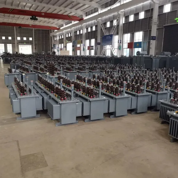
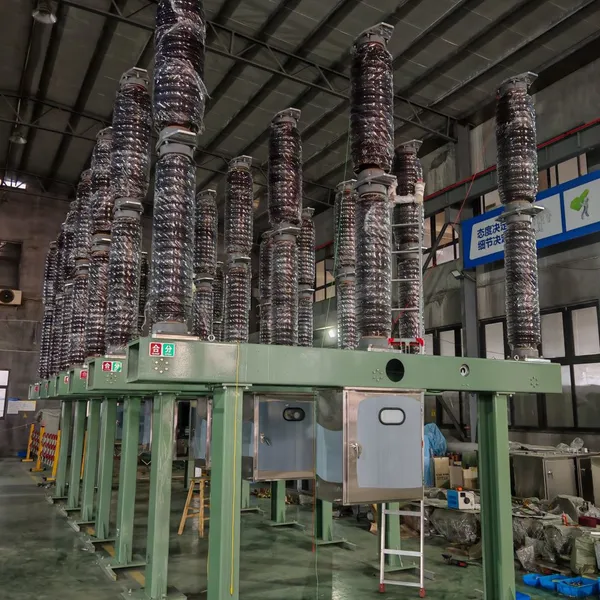
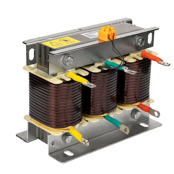
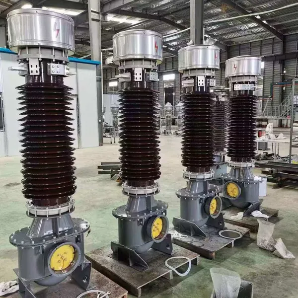
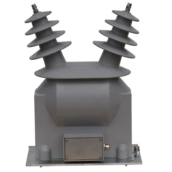
1. The principle of transformer: Transformer is a device that uses the principle of electromagnetic induction to change AC voltage and current. The main components are primary coil, secondary coil, and iron core (magnetic core). The following figure shows several transformers with different shapes.
2. The function of a transformer is to change the voltage: to increase or decrease the voltage, and to convert the electricity generated by the generator into a voltage level suitable for residential or industrial use through the processes of boosting, transmitting, and reducing the voltage. Variable current: Changing the magnitude of the current while changing the voltage. Isolation: Isolating the user system from the power supply system to reduce the scope of accidents.
What are the types of transformers
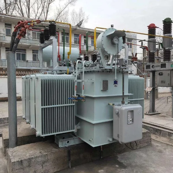
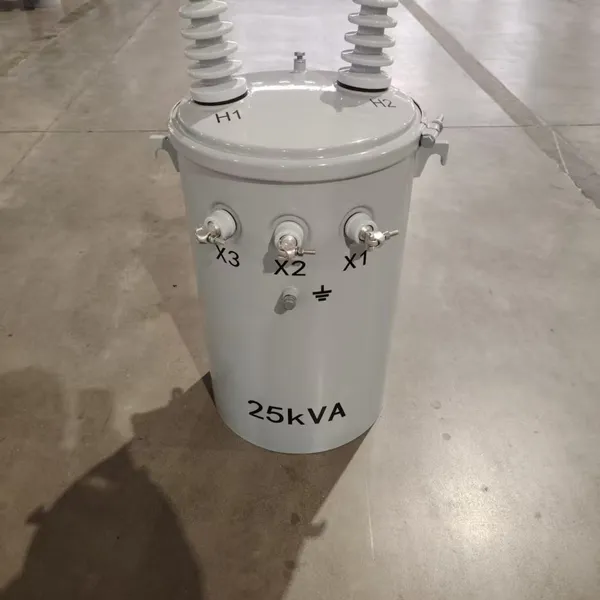
Divided by cooling method: A. Oil immersed transformer: a transformer that uses transformer oil as the insulation and cooling medium, with the iron core and coil fully immersed in the insulation oil. B. Dry type transformer: The iron core and coil are cast with epoxy resin material to provide insulation. According to the number of power phases, it can be mainly divided into single-phase transformers and three-phase transformers. A. The functional characteristics of a single-phase transformer are that it is a transformer with a single-phase primary winding. As shown in the figure, the primary winding and secondary winding of a single-phase transformer are both wound around the iron core. The primary winding is the AC voltage input terminal, and the secondary winding is the AC voltage output terminal. The output voltage of the secondary winding is proportional to the number of turns of the coil. A single-phase transformer can convert high voltage power supply into single-phase low voltage for various equipment use. For example, it can convert AC 6600V high voltage into AC 220V low voltage through a single-phase transformer to supply power to lighting fixtures or other equipment. Single phase transformers have the advantages of simple structure, small size, and low loss, making them suitable for use in low-voltage distribution lines with low loads (below 60Hz). The functional schematic diagram of single-phase transformer. Single phase transformers are commonly used in rural power transmission and distribution systems, as well as in the power supply of some lighting or small motors. Examples of their applications are shown in the figure. In addition, it can also be used as a power transformer in many electronic and electrical equipment.
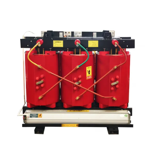
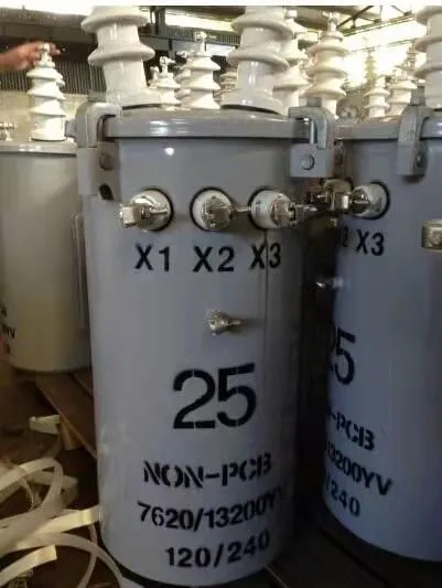
B. The functional characteristics of three-phase transformers. Three phase transformers are a type of transformer widely used in power equipment. A three-phase transformer is actually composed of three single-phase transformers of the same capacity, with the primary winding (high-voltage coil) being three-phase and the secondary winding (low-voltage coil) also being three-phase, as shown in the figure. The structural characteristics of three-phase transformers are mainly used for boosting or reducing voltage in three-phase power supply systems. A commonly used method is to convert high voltage of several thousand volts into low voltage of 380V, providing power supply for electrical equipment. The functional diagram of a three-phase transformer shows that it has a wide range of applications, such as substations, industrial and mining enterprises, construction sites, drainage and irrigation equipment, postal and telecommunications, textiles, railways, schools, hospitals, national defense, elevators, etc. It is also suitable for some low-voltage distribution lines with low power supply voltage and large fluctuations. Application examples of three-phase transformers
4. Representation method of transformer model
There are many types of transformers, and in order to distinguish between different types of transformers, letters or numbers are usually used to identify the model names of transformers. The model of a transformer is usually composed of letters and numbers, used to indicate the number of phases, cooling method, voltage regulation method, winding core material, winding connection method, and other related information of the transformer. Product Name: The product name of a transformer is usually represented by letters, indicating the coil coupling method, number of phases, cooling method, number of coils, coil wire material, voltage regulation method, and special purpose of the product, as shown in the table below. Design serial number: also known as technical serial number, represented by numbers, indicating different varieties of similar products to distinguish their external dimensions and performance indicators, sometimes omitted. Rated capacity: The rated capacity of a transformer is expressed in "kVA" and can be read as "kilovolt ampere". Transformers use kVA as the unit because in the absence of a determined load, the magnitude of active power (symbol P, unit kW) and reactive power (symbol Q, unit kvar) cannot be obtained. Only kVA can be used to represent power. For example, the output power of a 1kVA transformer is about 1kW. High voltage side rated voltage: The high voltage side rated voltage of a transformer is the rated voltage value input to the primary winding input terminal, usually represented by the letter "kV". For example, 10kV indicates that the primary winding of a transformer can input a voltage of 10kV.
5.Transformer primary and secondary rated voltage, rated capacity, wiring group, primary and secondary rated current, transformer impedance voltage, tap changer adjustment voltage range, operating environmental conditions, transformer oil model and weight, etc.
6. Symbol identification of transformers in circuits Transformers are generally used in control circuits and distribution circuits of electrical equipment, and are one of the commonly used devices in control circuits of electrical equipment. Therefore, understanding the symbol identification of transformers in circuits is also very important. Transformers are generally represented by the letter "T" in the circuit and marked with graphic symbols, as shown in the figure.
There are two general graphic symbols for transformers, which are used in distribution lines and electrical lines respectively. The voltage input terminal is the primary winding of the transformer, and the voltage output terminal is the secondary winding of the transformer. In addition, transformers with magnetic cores or center taps are also represented in their graphical symbols. The graphic symbol of a transformer with three windings. Some three-phase transformers can also reflect the connection method of the transformer in the graphic symbol, as shown in the following figure.
In actual power lines, there are two connection methods for single-phase transformers, namely series connection and parallel connection. Transformers can achieve a higher rated voltage when connected in series, and a higher rated current when connected in parallel. There are many windings inside a three-phase transformer, and the most commonly used connection method is the star (Y-shaped) connection. This structure refers to the primary winding of the three-phase transformer being connected in a Y-shaped manner, where the end of each winding is connected to the neutral point and the other end of the winding is connected to the corresponding line. The most commonly used star connection method for three-phase transformers in power lines is the Y-Y connection, where both the primary and secondary windings are connected in a Y-shaped manner. Three phase transformer Y-Y connection method
What are the components of a transformer
A. Main body of the device: including iron core, winding, insulation support B. Voltage regulating device: namely tap changer, (on load voltage regulating device and off excitation voltage regulating device) C. Oil tank and sheet shaped radiator (wings), sleeve D. Safety device: moisture absorber, gas relay, oil filter, temperature measuring instrument, etc.
8. What is the use of transformer oil? (1) Insulation function: Transformer oil has strong insulation performance, which generates sufficient insulation strength between the winding and the shell. Commonly seen are DB25 and DB45 models. (2) Heat dissipation function: Transformer oil naturally circulates between the body and the fin shaped radiator based on the principle of rising when heated, dissipating heat through the radiator and keeping the temperature of the coil not too high. (3) Arc extinguishing function: When operating the on load voltage regulating device, arc light will be generated when the tap changer is opened, and the transformer oil can extinguish the arc light, providing protection.
9. Function of oil storage tank (oil pillow) The oil pillow (oil storage tank) is installed diagonally above the oil tank and is connected to the oil pipe and the oil tank. When the volume of transformer oil expands and contracts with changes in oil temperature, the oil pillow plays a role in storing and replenishing oil. Prevent oil from being oxidized and dampened by contact with air. The oil pillow is equipped with an oil gauge tube, and some are also equipped with a liquid level indicator to observe changes in the oil level.
10. What is on load voltage regulation? On load voltage regulation is a voltage regulation method in which a transformer can change its voltage by switching the tap gear during load operation.
11. What are the losses of transformers during operation? Transformer losses include: no-load losses (iron losses): losses caused by eddy currents in the iron core, load losses (copper losses): losses caused by the resistance heating of the winding.
What is the function of a moisture absorber (respirator)?
A. Due to the constant temperature changes during the operation of the transformer, the oil level inside the transformer may rise or fall, and the gas must be discharged, otherwise the pressure will increase; It can be understood as the process of breathing, which plays a role in preventing direct contact between oil and air from deteriorating. B. Install a silicone canister on the exhalation channel of the oil. The transformer breathes through the silicone, and the discharged water is absorbed. When the water reaches a certain level, the color of the silicone will change from blue to red. At this time, the silicone needs to be replaced. As shown in the picture.
13. What is a gas relay? What is its function? Gas relay (also known as gas relay) is a protective device used in transformers, installed between the pipeline between the oil storage tank and the oil tank of the transformer. When the internal fault of the transformer causes the oil to decompose and produce gas or cause oil flow surge, the contact of the gas relay is activated, and the "heavy gas" trip signal and "light gas" alarm signal are sent to the duty personnel through the internal electrical common contact, reminding them that the transformer is abnormal or faulty.
Recently Posted
-
System scheme and primary structure of American standard medium and low voltage switchgear
July 1, 2026The system scheme for power distribution comprehensively reflects the direction of power flow, current distribution, short-circuit Read More
 -
IEC 17.5kV switchgear Guzhou Weng will speak on electrical June 28, 2026 05:03 2 people
June 30, 202617.5kV is the IEC standard voltage level, applied in power systems with voltages of 13.2/13.8/15kV. IEC 17.5kV metal enclosed swit Read More
 -
Design points of customized switchgear
June 30, 2026With the increasing demand for new energy and data centers, in addition to standardized products, there is a need for a large numb Read More
 -
Marine low-voltage switchgear
June 30, 2026Marine low-voltage switchgear needs to meet the special requirements of ship application systems, environments, etc., and develop Read More

Contact Us
Recommended Products
-
 Single Phase Oil Immersed Transformer 10KVA 15KVA 25KVA 37.5KVA Standard CompliantNegotiableMOQ: 2 Units
 -
Electrical Arc Furnace Transformers up to 120MVA - Certified for Steel Industry ApplicationsUS$ 8000 - 10000MOQ: 1 Unit
-
3-Phase Oil Type Transformer 5-Year Warranty With Load Test ReportUS$ 5428 - 5628MOQ: 1 Unit
-
Three Phase Oil Filled Transformer for Mining Operations Dust-Proof DesignUS$ 5428 - 5628MOQ: 1 Unit
-
HV Three Phase Oil Filled Transformer With ONAN Cooling 500kVA-2500kVAUS$ 5428 - 5628MOQ: 1 Unit
-
11/24/33KV High Voltage Isolation Switch With Mill Test ReportUS$ 800MOQ: 1 Unit
-
3-Pole Outdoor Isolation Switch With 5-Year Warranty and Compliance TestingUS$ 800MOQ: 1 Unit
-
YH5WZ 3KV-110KV Zinc Oxide Arrester for Power Station Outdoor High Voltage DistributionUS$ 21MOQ: 100 Units
-
Outdoor SF6 Load Break Switch LW30-72.5/1250A 24KV 630A 16KA Three PhaseUS$ 10000MOQ: 1 Unit
-
Input Line Reactor for CNC Machine Frequency Converters, 400V 60HzUS$ 65MOQ: 5 Units
-
Industrial Grade 35-220KV Oil-Immersed Current Transformer for SubstationsUS$ 480 - 500MOQ: 3 Units
-
LZZBJ9-20 Indoor 24kV High Voltage Cabinet Single-Phase 5-20 for Industrial Power SystemsUS$ 250MOQ: 3 Units
-
17.5 KV Full-enclosed Outdoor Epoxy Resin Casting and Double Pole Insulated Voltage TransformerUS$ 90 - 100MOQ: 1 Piece
-
Three Phase 30kVA SVC Voltage Regulator for Textile Manufacturing, Stable OutputUS$ 159MOQ: 10 Units
-
Amorphous Core 25kVA Transformer Compliant With IEC Standards for Power DistributionUS$ 1300 - 2900MOQ: 2 Units
-
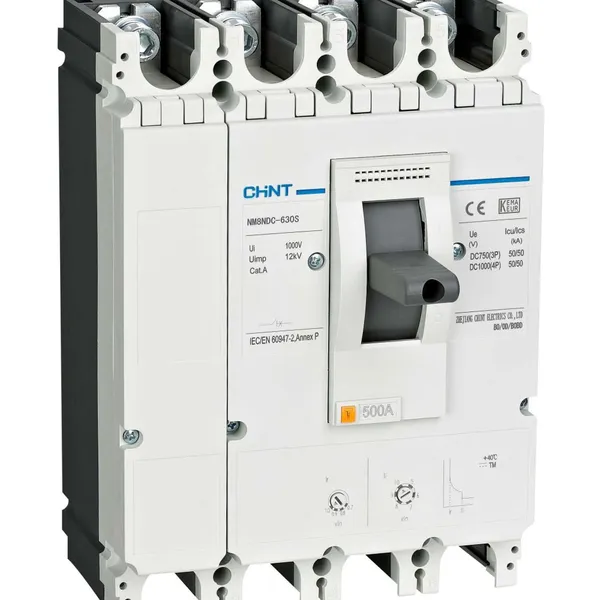
CHINT NM8NDC-630 DC 1000V/Ui High-Voltage Circuit Breaker With 630A Frame CurrentUS$ 425 - 625MOQ: 100 Units
-
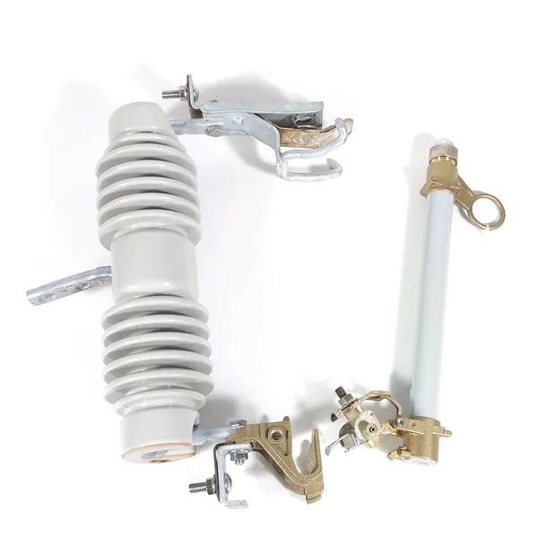
High Voltage Drop Out Fuse Cutout 33KV 27KV 24KV for Overhead LinesUS$ 35MOQ: 100 Units
-
TVR-10 KVA Automatic Voltage Stabilizer 220V ±0.5% Accuracy for Laboratory InstrumentsUS$ 103 - 123MOQ: 1 Unit
-
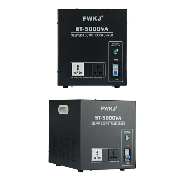
Universal 5000VA Voltage Transformer for International Appliances 110V-220VUS$ 102 - 107MOQ: 10 Units
-
500kV Three-Phase Oil-Immersed Auto Transformer 250MVA for Power GridsUS$ 800 - 9000MOQ: 1 Unit