
Design of IEC 17.5kV switchgear
17.5kV is the voltage level of rated voltage sequence 1 in IEC62271-1 standard, generally used in power systems with nominal voltages of 13.8 and 15kV. This voltage level is used in regions or countries such as South America, the Middle East, and the Philippines. Foreign customers come to China to purchase 17.5kV switchgear, while domestic manufacturers sell 24kV switchgear with large product sizes and high costs. The size of the 17.5kV switchgear produced by foreign manufacturers is consistent with that of 12kV, with a small size and insulation level that can meet the requirements of radar impulse withstand voltage of 95kV.
ABB、 Multinational companies such as Siemens and Schneider have introduced IEC standard 17.5kV circuit breakers and switchgear products into China and converted them into Chinese standard 12kV products. Therefore, the size is consistent with domestic 12kV products. The smallest ones, such as ABB's 550mm wide switchgear, are sold in countries such as Europe and South America with a rated voltage of 17.5kV. The rated short-time power frequency withstand voltage of 17.5kV circuit breakers and switchgear according to IEC standards is 38kV, which is lower than the 42kV of 12kV according to GB standards. However, the rated lightning impulse withstand voltage is 95kV, which is much higher than the 75kV rated lightning impulse withstand voltage of 12kV circuit breakers and switchgear according to GB standards. It is difficult to maintain consistent size.
The IEC standard specifies a minimum air clearance of 160mm for 95kV lightning impulse withstand voltage;
Therefore, for a 600mm wide switchgear, the phase to phase distance is 150mm, which cannot guarantee a net distance of 160mm. However, composite insulation such as heat shrink tubing, epoxy resin vulcanization coating, and insulation boards can be used to reduce the distance. By using heat shrink tubing from companies such as Ruikan as composite insulation, the net distance can be significantly reduced. 1250A uses two 50 × 8 copper bars per phase, wrapped with Raychem 25kV thermoplastic sleeve BPTM. The phase to phase clearance can be greater than 95mm, which meets Raychem's technical specifications for a minimum of 85mm between phases. The minimum clearance between copper bars relative to ground is 115mm, which is also greater than the required 105mm. The requirements for net distance of Ruikan BPTM heat shrink tubing are shown in the table. Requirements for static distance of Ruikan BPTM heat shrink tubing
The working temperature range of Ruikan heat shrink tubing is up to 125 degrees. If used for a long time below this temperature, the risk of heat shrink tubing rupture and insulation failure is very low. Ruikan has evidence of accelerated aging tests. Through optimized design, 2 50 × 8 copper bars are used for each phase, and the temperature rise under 60Hz 1250A current is only about 60k, which is lower than the maximum heat-resistant temperature limit and will not cause cracking problems. The reason for the occurrence of heat shrink tubing cracking and insulation failure is that some companies use substandard materials and low product quality in their copper bars, resulting in excessively high temperatures in the copper bars and low heat-resistant temperatures in the thermoplastic sleeves.
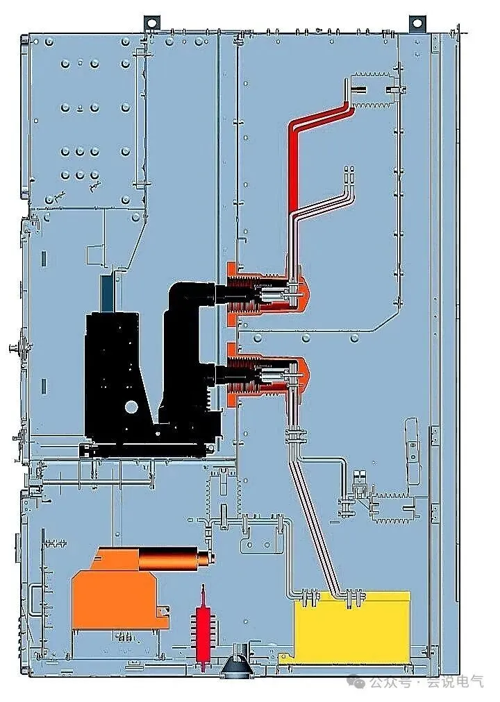
The standard 12kV switchgear is applied to 17.5kV, and the weak points of insulation are mainly concentrated in three locations: the insulation of the static contact to the valve when the circuit breaker is in the test position, the insulation of the circuit breaker when it is in the working position, and the grounding switch. (1) The withstand voltage circuit breaker of the static contact to the valve discharge during the test position. Due to the fact that the distance between the valve plate and the static contact is only 125mm when the valve is closed and 115mm when the current is high, the 95kV lightning impulse withstand voltage cannot pass through. Due to IEC standards requiring switchgear to meet LSC 2B PM level requirements, it must be a metal valve. The measures taken mainly include: 1) Epoxy vulcanization valve can solve the pressure resistance problem, but vulcanization quality is the key. Due to the 95kV lightning impulse withstand voltage, the thinnest part of the valve vulcanization must have a thickness greater than 1.5mm. However, it is difficult to ensure the vulcanization thickness of thin steel plates, and the thickness varies. In addition, when there are bumps or other situations, the epoxy vulcanization layer is easily peeled off, causing insulation damage and low reliability; 2) The insulation board plus steel plate mode uses SMC or other insulation boards on the side facing the static contact, while a layer of metal plate is attached on the outside. This type of valve has a large thickness and weight, making it difficult to operate the valve lifting mechanism. In addition, the insulation board induces charges and lacks reliable grounding; 3) The laminated aluminum foil flap can meet the requirements of metal flaps, and has good insulation performance, stable thickness, and reliable quality. The internal laminated aluminum foil and flap guide plate are reliably grounded, and will not cause vulcanization detachment due to collision.
2) When the circuit breaker is in the working position, it was found during the test that the contact box was discharging. Due to the incomplete insulation at the connection between the circuit breaker contact arm and the pole, discharge occurs between the contact arm root and the installation bolt of the contact box, or through the plum blossom contact along the inner umbrella skirt surface to the installation bolt of the contact box. After finding the discharge path, the contact box is redesigned accordingly, and the contact arm sleeve is designed to cover the middle position of the plum blossom contact, completely blocking the discharge path. The measures taken mainly include: 1) The contact box adopts a design of fixing from the back of the plate with bolts, increasing the flange surface and enlarging the installation holes of the contact box on the steel plate; 2) Increased the internal climbing distance to make it greater than 315mm; 3) Raised the protruding side of the outgoing line to form an insulation barrier between the knife of the grounding switch and the copper bar of the contact box when it is opened; 4) Using high-quality Huntsman epoxy resin material and passing the ASTM D2303 standard electric trace resistance test, effectively preventing arc propagation.
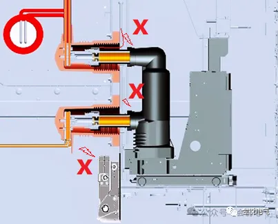
In this way, there is sufficient insulation shielding at the front to block the discharge from the base of the circuit breaker contact arm to the contact box mounting plate. The discharge path from the plum blossom contact along the inner wall of the contact box to the mounting plate is also extended, and the discharge path between the grounding switch blade and the contact box outlet is also blocked. After taking these measures, the 95kV lightning impulse withstand voltage test passed smoothly.
3) The size of the voltage resistant grounding switch of the grounding switch needs to be consistent with 12kV. Due to the fact that the static contact of the grounding switch is always in a high voltage state during the operation of the switchgear, the lightning impulse withstand voltage to ground and between phases needs to be solved. The insulation cover or insulation partition can be installed between phases to solve this problem. However, the static contact of the grounding switch is 130mm away from the ground, which does not meet the requirement of 160mm, and an insulation partition cannot be installed between the contact and the ground. Therefore, the following measures are mainly taken: 1) The static contact of the grounding switch adopts Ø 12 cylindrical contact fingers; 2) Add a thin flat plate with a uniform electric field at the main shaft of the grounding switch. This forms a uniform electric field between the cylinder and the flat plate, fundamentally solving the problem that the original grounding switch cannot withstand 95kV lightning impulse voltage. The insulation optimization diagram of the 17.5kV rated voltage grounding switch is shown in the following figure.
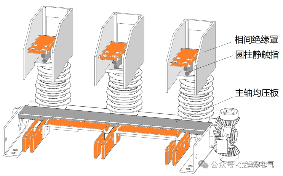
Therefore, using a standard 12kV switchgear without changing the size of the switchgear (width can be smaller, such as 1250A/31.5kA width of 600mm, 2000A/40kA width of 750mm), through the above optimization, it can pass the 17.5kV insulation test and be smoothly applied to overseas projects.
Recently Posted
-
System scheme and primary structure of American standard medium and low voltage switchgear
July 1, 2026The system scheme for power distribution comprehensively reflects the direction of power flow, current distribution, short-circuit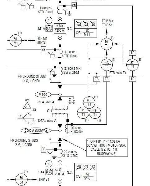 Read More
 -
IEC 17.5kV switchgear Guzhou Weng will speak on electrical June 28, 2026 05:03 2 people
June 30, 202617.5kV is the IEC standard voltage level, applied in power systems with voltages of 13.2/13.8/15kV. IEC 17.5kV metal enclosed swit Read More
 -
Design points of customized switchgear
June 30, 2026With the increasing demand for new energy and data centers, in addition to standardized products, there is a need for a large numb Read More
 -
Marine low-voltage switchgear
June 30, 2026Marine low-voltage switchgear needs to meet the special requirements of ship application systems, environments, etc., and develop Read More

Contact Us
Recommended Products
-
 Single Phase Oil Immersed Transformer 10KVA 15KVA 25KVA 37.5KVA Standard CompliantNegotiableMOQ: 2 Units
 -
Electrical Arc Furnace Transformers up to 120MVA - Certified for Steel Industry ApplicationsUS$ 8000 - 10000MOQ: 1 Unit
-
3-Phase Oil Type Transformer 5-Year Warranty With Load Test ReportUS$ 5428 - 5628MOQ: 1 Unit
-
Three Phase Oil Filled Transformer for Mining Operations Dust-Proof DesignUS$ 5428 - 5628MOQ: 1 Unit
-
HV Three Phase Oil Filled Transformer With ONAN Cooling 500kVA-2500kVAUS$ 5428 - 5628MOQ: 1 Unit
-
11/24/33KV High Voltage Isolation Switch With Mill Test ReportUS$ 800MOQ: 1 Unit
-
3-Pole Outdoor Isolation Switch With 5-Year Warranty and Compliance TestingUS$ 800MOQ: 1 Unit
-
YH5WZ 3KV-110KV Zinc Oxide Arrester for Power Station Outdoor High Voltage DistributionUS$ 21MOQ: 100 Units
-
Outdoor SF6 Load Break Switch LW30-72.5/1250A 24KV 630A 16KA Three PhaseUS$ 10000MOQ: 1 Unit
-
Input Line Reactor for CNC Machine Frequency Converters, 400V 60HzUS$ 65MOQ: 5 Units
-
Industrial Grade 35-220KV Oil-Immersed Current Transformer for SubstationsUS$ 480 - 500MOQ: 3 Units
-
LZZBJ9-20 Indoor 24kV High Voltage Cabinet Single-Phase 5-20 for Industrial Power SystemsUS$ 250MOQ: 3 Units
-
17.5 KV Full-enclosed Outdoor Epoxy Resin Casting and Double Pole Insulated Voltage TransformerUS$ 90 - 100MOQ: 1 Piece
-
Three Phase 30kVA SVC Voltage Regulator for Textile Manufacturing, Stable OutputUS$ 159MOQ: 10 Units
-
Amorphous Core 25kVA Transformer Compliant With IEC Standards for Power DistributionUS$ 1300 - 2900MOQ: 2 Units
-
CHINT NM8NDC-630 DC 1000V/Ui High-Voltage Circuit Breaker With 630A Frame CurrentUS$ 425 - 625MOQ: 100 Units
-
High Voltage Drop Out Fuse Cutout 33KV 27KV 24KV for Overhead LinesUS$ 35MOQ: 100 Units
-
TVR-10 KVA Automatic Voltage Stabilizer 220V ±0.5% Accuracy for Laboratory InstrumentsUS$ 103 - 123MOQ: 1 Unit
-
Universal 5000VA Voltage Transformer for International Appliances 110V-220VUS$ 102 - 107MOQ: 10 Units
-
500kV Three-Phase Oil-Immersed Auto Transformer 250MVA for Power GridsUS$ 800 - 9000MOQ: 1 Unit