
 Business License

Copper bar support
Regarding the mechanical and thermal effects of short-circuit current, the corresponding calculation standard GB/T 35698.1 is for short-circuit current effect calculation. GB/T35698.1 is specifically used to calculate the electric force acting on the busbar of switchgear under short-circuit current, and then verify whether the insulation support meets the requirements based on the electric force. Equivalent to IEC60865-1
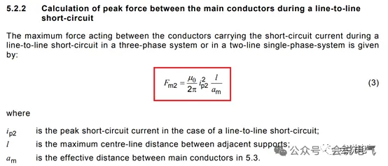
According to the calculation formula, the square of electric force and short-circuit current is directly proportional to the distance between adjacent supports, and inversely proportional to the phase to phase distance.
The calculation example is as follows: the support spacing is 400mm, the phase spacing is 80mm, and the experimental parameters are shown in the following table:
According to the standard calculation, the electric power Fm3=μ 0/2 π * 1.732/2 * ip32 * l/am=4 π x10-7/2 π * 1.732/2 * 1050002 * 0.4/0.08
=From the calculation formula of 19095N, it can be seen that the force exerted on the busbar clamp is proportional to the sum of the square of the peak short-circuit current and the distance between the supports. The force and support strength that the busbar clamp can withstand are fixed. Therefore, the support distance of the busbar clamp under different short-circuit current conditions can be simply calculated. For example, if the busbar clamp passes the short-term withstand current test with a peak withstand of 105kA and a support distance of 400mm, how much of the support distance can pass the peak withstand test with 143kA? The simple calculation is as follows:
110 * 110 * 400/143/143=236.68mm requires support spacing that cannot exceed 236mm.
What is the maximum distance for a busbar clamp that can withstand a short-circuit peak of 176kA with a support spacing of 500mm and a short-circuit current of 100kA? Calculate
176*176*500/220/220=320mm
For the support spacing, it must be clearly defined as the basis of design, especially for non-standard designs, to ensure that the product meets the short-term withstand current requirements.
The IEC60865 calculation standard is also applicable to medium voltage switchgear. For the support of busbars, the electric force acting on insulators is first calculated based on the phase spacing and support spacing, and the bending strength of insulators is checked. The maximum distance required for support can also be calculated based on the required stress and the bending resistance of the insulator.
Low voltage cabinets generally have a high peak withstand current, up to 330kAp, and a small phase to phase distance. They are supported by bus clamps, so the required spacing between bus clamp supports is also relatively small. If the spacing is too large, the bus clamp cannot withstand the electric force of the current and will collapse.
After the dynamic stability test of the vertical busbar 80kA 176kA in the MW scheme of the old B cabinet, the busbar clamp was opened. This is because the phase spacing is small and the short-circuit current of 176kA is very large, resulting in a very large electric force. The distance between the vertical busbar and the horizontal busbar connection without support is too large, so the electric force exceeds the force that the insulation support can withstand. Even if insulation screws are used for reinforcement, it still cannot withstand it. Many low-voltage cabinets have failed peak withstand tests in this area, so special attention should be paid.
There are many forms of busbar clamps, including SMC material half clamping form, comb shaped busbar clamp form, busbar frame form, and insulator form.
By using reinforced nylon and stainless steel plate support, electric power is transmitted to the steel plate through nylon, resulting in high strength and allowing for large spacing.
It is worth noting that the busbar adopts a grouping form, such as 6300A 150kA/330kA. The busbar is divided into two groups of 12 10x40mm busbars, with 6 busbars in each group. Each group A, B, and C is relatively independent, so the short-circuit current is diverted, which is equivalent to each group of busbars only bearing 165kA.
The bending resistance of medium voltage insulators is generally greater than 8000N, and some thick insulators can even reach 20000 N, so the spacing between supports can be greatly increased. Therefore, it can be seen that many manufacturers' switchgear main busbars do not require insulator support, especially those with 31.5kA (peak withstand current of 80kA) and below. Generally speaking, the phase spacing is about 300mm, and the main busbar can be supported by branch busbars without separate support. The phase spacing is 300mm, the insulator has a bending resistance of 10000N, and under a 30% safety margin, the maximum insulation support spacing for 63kA peak withstand current is 3.2 meters, for 100kA it is 1.3 meters, and for 125kA it is 0.8 meters.
The support of the busbar needs to be calculated and simulated based on the layout of the busbar. After experimental verification, empirical formula calculations can only be used as design references.
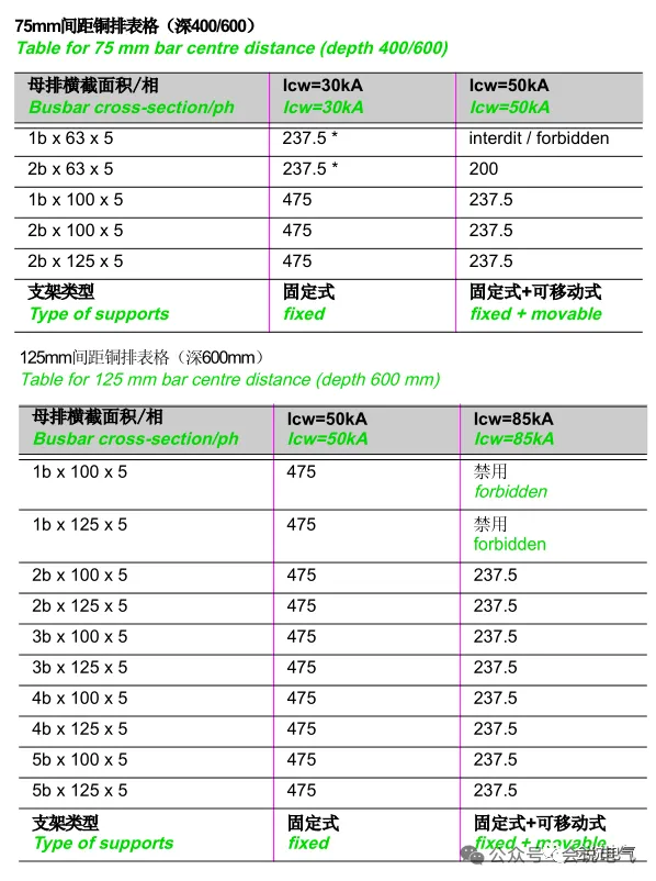
Insulation support does not necessarily have to be completely rigid, that is, the copper bars are fixed still, but can also have floating ones. For example, cabinet B has a movable bracket that only fixes three phases and is not fixed to the cabinet. It is normal for the peak electric force to cause a slight displacement, but it cannot damage the insulation structure or reduce the insulation capacity. For example, some medium voltage switchgear bus bushings can also withstand electric force, but silicone rubber separators cannot.
Recently Posted
-
Standard compliance
August 19, 2026The previous netizen said: I think there are printing related standards on the product brand, so I think this equipment has passed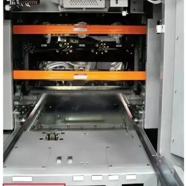 Read More
 -
Primary contact of American standard medium voltage circuit breaker
August 17, 2026IEEE C37.20.2 standard, primary contact of withdrawable circuit breaker for medium voltage metal armored switchgear.Unlike domesti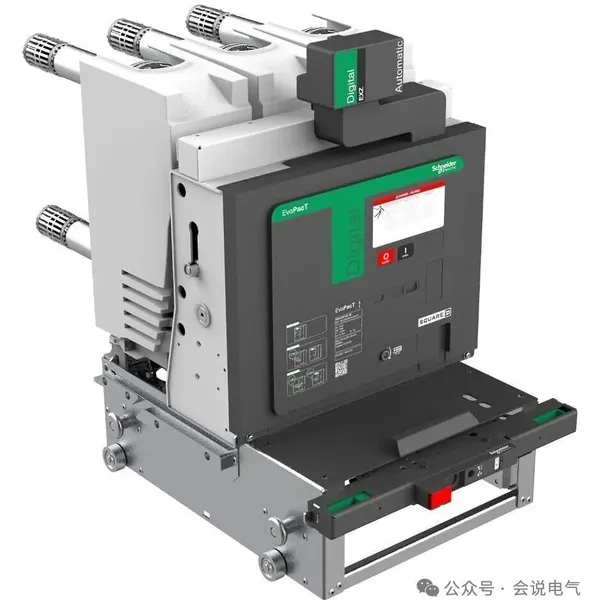 Read More
 -
Isolation handcart
August 17, 2026Isolation refers to the separation of two parts to meet safety requirements. Electrical isolation achieves a safe electrical gap b Read More
 -
Universal American standard medium voltage armored switchgear
August 17, 2026Unlike domestic medium voltage switchgear, which are all KYN28 mid mounted cabinets with the same structural layout and even size.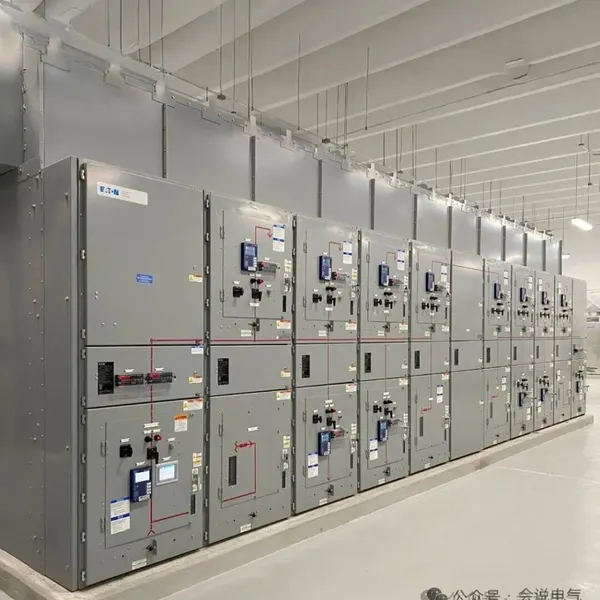 Read More

Contact Us
Recommended Products
-
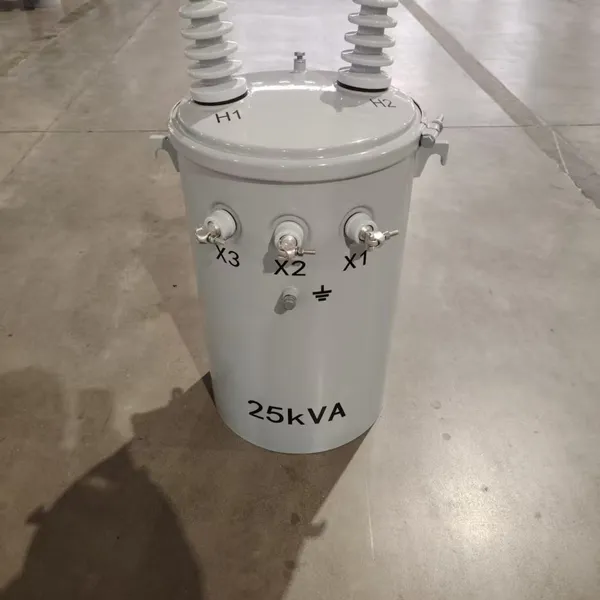
 Single Phase Oil Immersed Transformer 10KVA 15KVA 25KVA 37.5KVA Standard CompliantNegotiableMOQ: 2 Units
 -
Electrical Arc Furnace Transformers up to 120MVA - Certified for Steel Industry ApplicationsUS$ 8000 - 10000MOQ: 1 Unit
-
3-Phase Oil Type Transformer 5-Year Warranty With Load Test ReportUS$ 5428 - 5628MOQ: 1 Unit
-
Three Phase Oil Filled Transformer for Mining Operations Dust-Proof DesignUS$ 5428 - 5628MOQ: 1 Unit
-
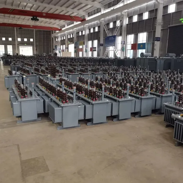
HV Three Phase Oil Filled Transformer With ONAN Cooling 500kVA-2500kVAUS$ 5428 - 5628MOQ: 1 Unit
-
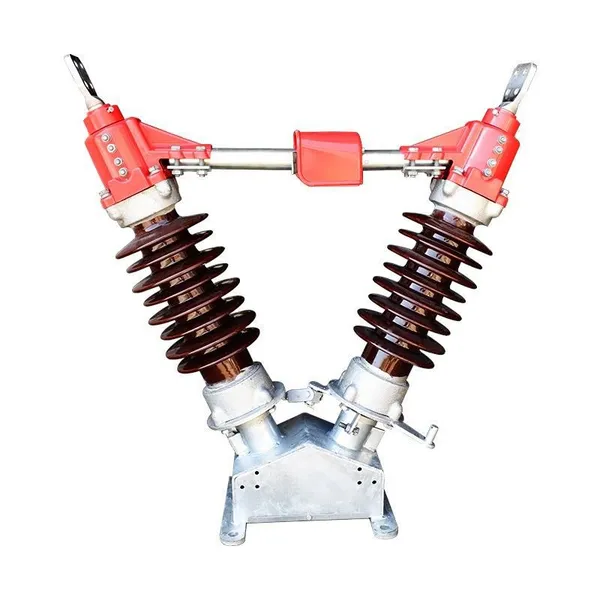
11/24/33KV High Voltage Isolation Switch With Mill Test ReportUS$ 800MOQ: 1 Unit
-
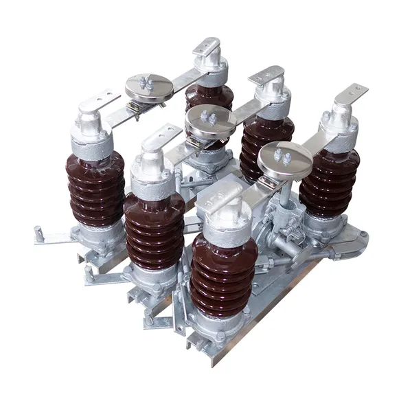
3-Pole Outdoor Isolation Switch With 5-Year Warranty and Compliance TestingUS$ 800MOQ: 1 Unit
-
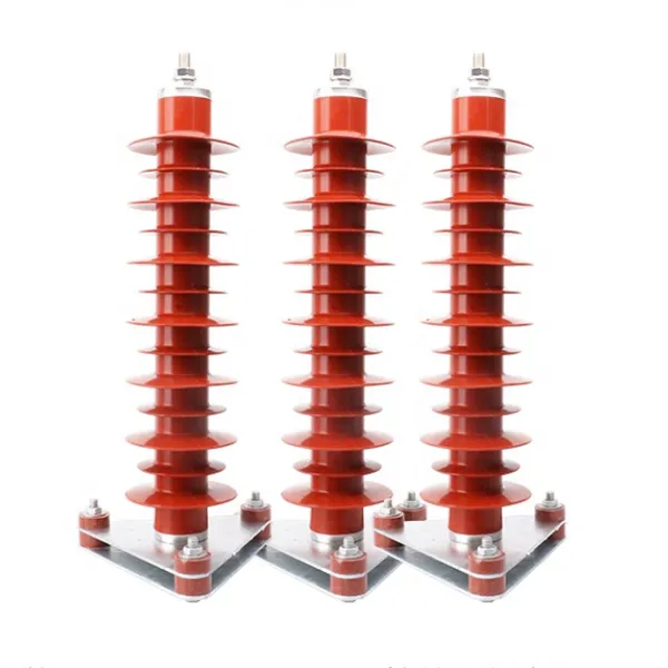
YH5WZ 3KV-110KV Zinc Oxide Arrester for Power Station Outdoor High Voltage DistributionUS$ 21MOQ: 100 Units
-
Outdoor SF6 Load Break Switch LW30-72.5/1250A 24KV 630A 16KA Three PhaseUS$ 10000MOQ: 1 Unit
-
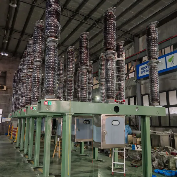
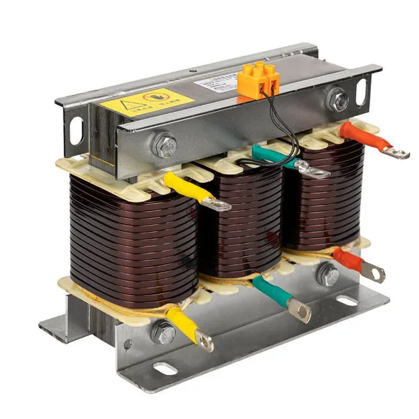
Input Line Reactor for CNC Machine Frequency Converters, 400V 60HzUS$ 65MOQ: 5 Units
-
Industrial Grade 35-220KV Oil-Immersed Current Transformer for SubstationsUS$ 480 - 500MOQ: 3 Units
-
LZZBJ9-20 Indoor 24kV High Voltage Cabinet Single-Phase 5-20 for Industrial Power SystemsUS$ 250MOQ: 3 Units
-
17.5 KV Full-enclosed Outdoor Epoxy Resin Casting and Double Pole Insulated Voltage TransformerUS$ 90 - 100MOQ: 1 Piece
-
Three Phase 30kVA SVC Voltage Regulator for Textile Manufacturing, Stable OutputUS$ 159MOQ: 10 Units
-
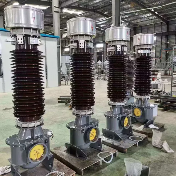
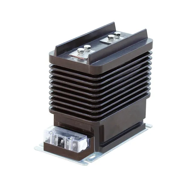
Amorphous Core 25kVA Transformer Compliant With IEC Standards for Power DistributionUS$ 1300 - 2900MOQ: 2 Units
-
CHINT NM8NDC-630 DC 1000V/Ui High-Voltage Circuit Breaker With 630A Frame CurrentUS$ 425 - 625MOQ: 100 Units
-
High Voltage Drop Out Fuse Cutout 33KV 27KV 24KV for Overhead LinesUS$ 35MOQ: 100 Units
-
TVR-10 KVA Automatic Voltage Stabilizer 220V ±0.5% Accuracy for Laboratory InstrumentsUS$ 103 - 123MOQ: 1 Unit
-
Universal 5000VA Voltage Transformer for International Appliances 110V-220VUS$ 102 - 107MOQ: 10 Units
-
500kV Three-Phase Oil-Immersed Auto Transformer 250MVA for Power GridsUS$ 800 - 9000MOQ: 1 Unit