
Internal arc pressure release of multi-layer cabinets
The demand for double-layer circuit breaker switchgear and three-layer circuit breaker switchgear in the industrial field has never stopped
And the internal arc capability is also a necessary requirement in the industrial field, which brings up the problem of how to meet the requirements of compact multi-layer and resist internal arc faults.
Explosion is caused by the enormous energy that cannot be released from the enclosed space. The internal arc fault energy can reach several megajoules. If there is no pressure release outlet in the compartment, it will explode into pieces. However, with relatively weak pressure relief cover plates and release channels, pressure can be released at weak points under low pressure in the early stage without damaging the compartment. And a dedicated separate channel can prevent damage to other compartments.
For the arrangement of upper and lower circuit breakers, the switch cabinet in the middle instrument room serves as a pressure release channel through the rear space of the instrument room. The lower handcart compartment, busbar compartment, and the second layer equipment of the three-layer switch cabinet can also release internal arc pressure through this compartment.
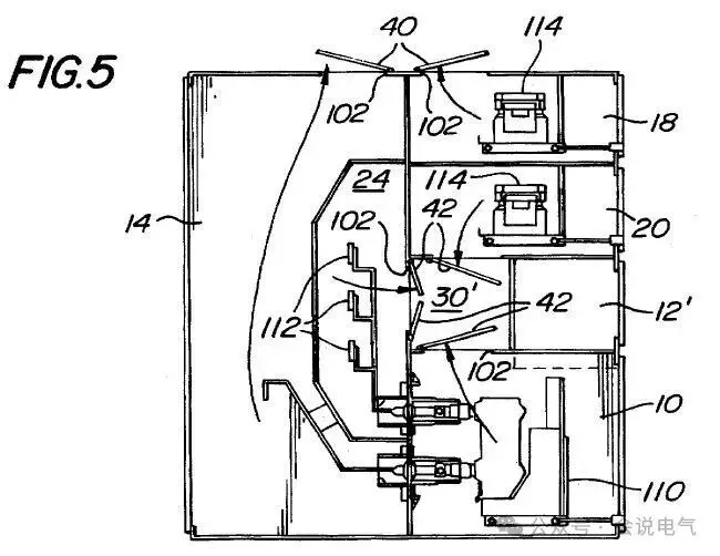
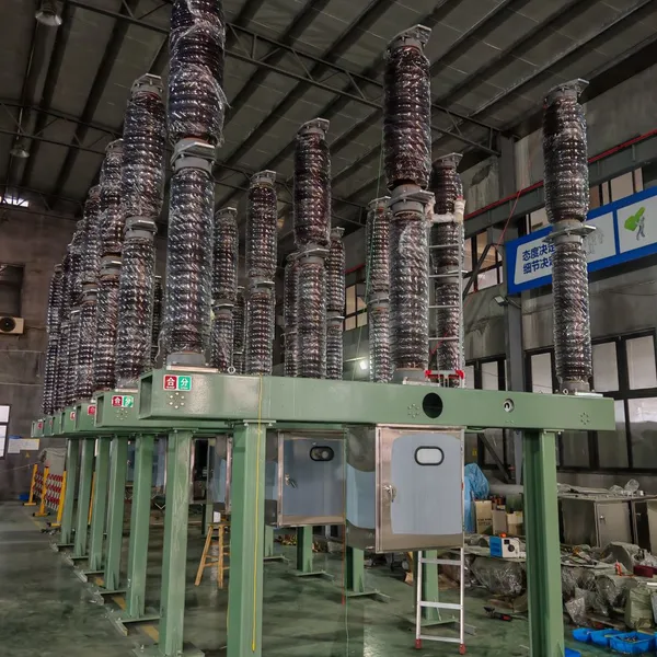
IEEE C37.20.2 internal arc level switchgear can be equipped with 4-layer voltage transformers VT, power transformers CPT, high-voltage fuses Fuse and other functional handcarts.
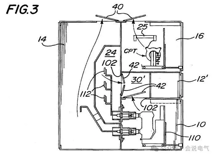
IEEE C37.20.2 internal arc level switchgear can be equipped with 4-layer voltage transformers VT, power transformers CPT, high-voltage fuses Fuse and other functional handcarts.
Internal faults and arcing in the lower cable compartment will inevitably cause significant damage and affect other parts of the cabinet, leading to further escalation of the accident
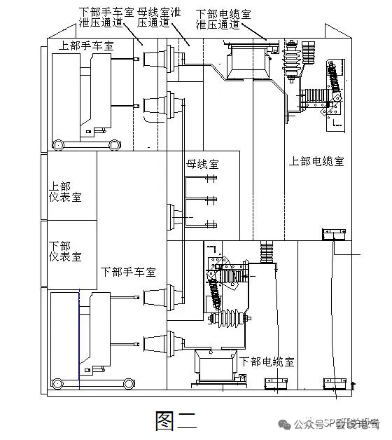
Figure 2 shows a product from a certain company, whose main busbar is located in the same position as other switchgear, making it easy to merge with high current switchgear, F-C cabinets, etc. without the need for other transfer cabinets. Due to the use of epoxy resin vulcanization coating technology for insulation of the main busbar, its phase to phase and ground distance are relatively small, and the busbar room is also smaller than domestic cabinet types. At the same time, its handcart is arranged at the top and bottom, and the instrument room is located in the middle of the cabinet. The upper and lower circuit instrument rooms are arranged separately, which is not easy to cause wiring errors. Each functional compartment is equipped with a pressure release channel, which is located on the right side of the cabinet and on one side of the grounding switch operating mechanism. This cabinet type is designed according to the internal fault requirement of 0.1s 25kA. In a switchgear with a width of 840mm, the cross-sectional area of the pressure release channel is generally 100mm x 200mm On the left and right sides, the pressure release plate on the top of the cabinet is not completely fixed. One side is fixed with bolts, and the other side is fixed with bolts on the slotted hole with a gap. The fixed end of the bolt has a row of long waist holes to form a weak point, which is easy to open when the pressure rises rapidly. Generally speaking, 0.1 seconds is far from enough. When a malfunction occurs, energy quickly accumulates in a short period of time, usually reaching maximum pressure in 10 seconds. This causes a large amount of hot gas to accumulate inside, behind, on, and on all sides of the equipment, posing a major threat to the operator. At the same time, the heat will burn through the steel casing. So the duration of internal faults that the equipment can withstand should be long enough, and a 1-second test is necessary.
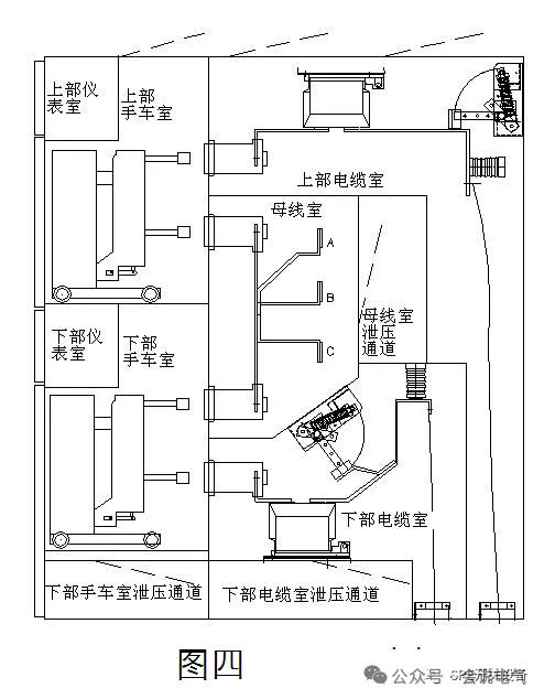
Figure 4 shows a double-layer cabinet designed taking into account the above factors. One major feature of this cabinet is that it ensures that each compartment has an independent pressure release channel. In the case of a row of cabinets, the lower part of the handcart compartment, the lower part of the cable compartment, and the rear part of the busbar compartment are all connected as pressure release channels. Energy is released through the pressure relief cover plates on both sides of the side cabinet. However, during design, it should be ensured that too many components are not arranged on the bottom plate, and there should also be space for pressure relief on the front bottom plate of the handcart. The relative position of the upper handcart of the cabinet is not high, only about 1200mm, which is convenient for operation, on-site observation, and maintenance. At the same time, the upper grounding switch is operated through a crank arm, and the operating position is also relatively low. The position of the main busbar is basically the same as other cabinet types, which can ensure that there is no need to transfer cabinets to connect the main busbar. The instrument rooms are located on the upper part of the two handcart rooms, ensuring the relative independence of component layout and wiring.
Recently Posted
-
Addition of foreign projects
June 1, 2026Foreign projects require mechanical key interlocking, and foreign customers have relatively high safety requirements. In addition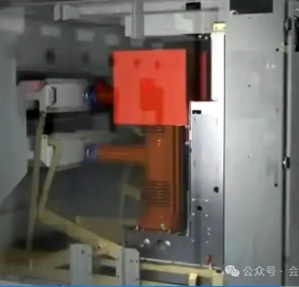 Read More
 -
Typical layout of American standard 27/38kV switchgear
June 1, 2026Different switch cabinet standards and application habits result in different layout of the system's primary scheme. For conve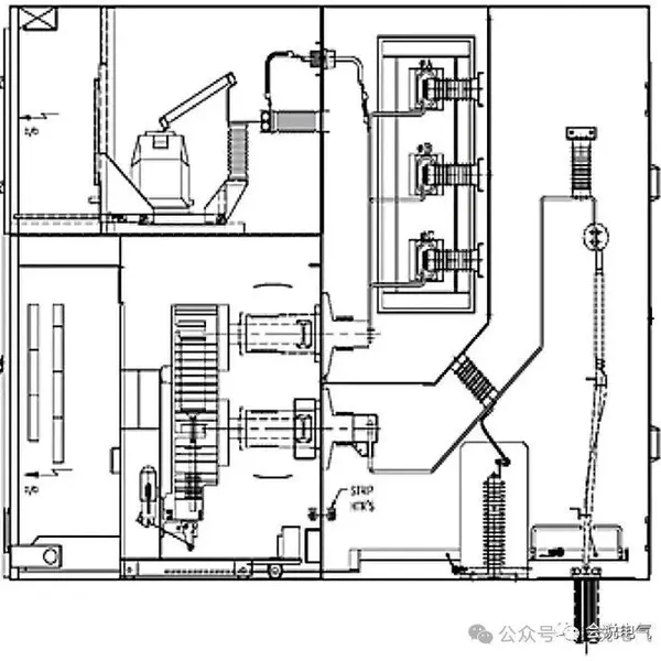 Read More
 -
Subtraction of foreign projects
May 29, 2026Mobile payment is not popular abroad. Chinese people value simplicity and convenience, while foreigners value safety and reliabili Read More
 -
Grounding switch for GE switchgear SECOGEAR
May 28, 2026The GE SECOGEAR series medium voltage armored switchgear adopts JNH1/4 type grounding switch from domestic 12/24/40.5kV to IEC 17.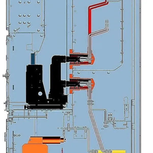 Read More

Contact Us
Recommended Products
-
 Single Phase Oil Immersed Transformer 10KVA 15KVA 25KVA 37.5KVA Standard CompliantNegotiableMOQ: 2 Units
 -
Electrical Arc Furnace Transformers up to 120MVA - Certified for Steel Industry ApplicationsUS$ 8000 - 10000MOQ: 1 Unit
-
3-Phase Oil Type Transformer 5-Year Warranty With Load Test ReportUS$ 5428 - 5628MOQ: 1 Unit
-
Three Phase Oil Filled Transformer for Mining Operations Dust-Proof DesignUS$ 5428 - 5628MOQ: 1 Unit
-
HV Three Phase Oil Filled Transformer With ONAN Cooling 500kVA-2500kVAUS$ 5428 - 5628MOQ: 1 Unit
-
11/24/33KV High Voltage Isolation Switch With Mill Test ReportUS$ 800MOQ: 1 Unit
-
3-Pole Outdoor Isolation Switch With 5-Year Warranty and Compliance TestingUS$ 800MOQ: 1 Unit
-
YH5WZ 3KV-110KV Zinc Oxide Arrester for Power Station Outdoor High Voltage DistributionUS$ 21MOQ: 100 Units
-
Outdoor SF6 Load Break Switch LW30-72.5/1250A 24KV 630A 16KA Three PhaseUS$ 10000MOQ: 1 Unit
-
Input Line Reactor for CNC Machine Frequency Converters, 400V 60HzUS$ 65MOQ: 5 Units
-
Industrial Grade 35-220KV Oil-Immersed Current Transformer for SubstationsUS$ 480 - 500MOQ: 3 Units
-
LZZBJ9-20 Indoor 24kV High Voltage Cabinet Single-Phase 5-20 for Industrial Power SystemsUS$ 250MOQ: 3 Units
-
17.5 KV Full-enclosed Outdoor Epoxy Resin Casting and Double Pole Insulated Voltage TransformerUS$ 90 - 100MOQ: 1 Piece
-
Three Phase 30kVA SVC Voltage Regulator for Textile Manufacturing, Stable OutputUS$ 159MOQ: 10 Units
-
Amorphous Core 25kVA Transformer Compliant With IEC Standards for Power DistributionUS$ 1300 - 2900MOQ: 2 Units
-
CHINT NM8NDC-630 DC 1000V/Ui High-Voltage Circuit Breaker With 630A Frame CurrentUS$ 425 - 625MOQ: 100 Units
-
High Voltage Drop Out Fuse Cutout 33KV 27KV 24KV for Overhead LinesUS$ 35MOQ: 100 Units
-
TVR-10 KVA Automatic Voltage Stabilizer 220V ±0.5% Accuracy for Laboratory InstrumentsUS$ 103 - 123MOQ: 1 Unit
-
Universal 5000VA Voltage Transformer for International Appliances 110V-220VUS$ 102 - 107MOQ: 10 Units
-
500kV Three-Phase Oil-Immersed Auto Transformer 250MVA for Power GridsUS$ 800 - 9000MOQ: 1 Unit