
Insulation test of circuit breaker cabinet
Whether it is a circuit breaker or a grounding switch, they can pass the insulation withstand voltage test separately, but once they are placed in the switchgear, they cannot pass the withstand voltage test.
We may say that there is a problem with the insulation of the switchgear, but the insulation withstand voltage test of the switchgear alone can also pass smoothly.
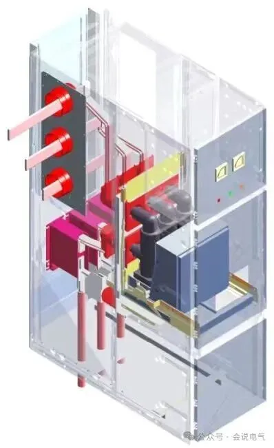
There are actually several issues with this. Firstly, circuit breakers, grounding switches, and other components are placed in the air and subjected to voltage withstand tests separately. There is no grounding body around them, and the grounding body of the circuit breaker handcart is only the frame, which means that the contact arm, pole, etc. only bear insulation voltage to the frame. When the circuit breaker is placed in the cabinet, it is not only to the frame, but also to the two side panels of the switch cabinet, the contact box installation board, the valve and its operating mechanism, and the IP protection board, etc. These are all grounding bodies and will produce discharge circuits
Simply put, the voltage between phase and ground divided by the net air distance between phase and ground equals the electric field strength between phase and ground. In a slightly uneven electric field, the electric field strength in the air cannot exceed 3kV per millimeter. If 75kV/125mm=0.6kV/mm, it is much smaller than 3kV. The distance between the contact arms of phase A and C of the circuit breaker in the air and the grounding body is large, the electric field strength naturally decreases. However, with the addition of the grounding body on the side plate, the electric field strength naturally increases.
This involves a concept of non-uniform electric field, which refers to an electric field with equal magnitude and direction between two voltage differences. In addition to uniform electric fields, there are also slightly non-uniform electric fields and non-uniform electric fields. Simply put, the electric field lines of a uniform electric field are parallel, while the electric field lines of an non-uniform electric field are divergent.
The electric field non-uniformity coefficient is used to determine the degree of electric field uniformity. The electric field uniformity coefficient is the ratio between the maximum electric field strength and the average electric field in the electric field. As the concept above suggests, if the electric field is uniform in size, direction, and everywhere, then the maximum electric field and the average electric field are consistent, which is called a uniform electric field. In theory, only the electric field between two infinitely large parallel planes is uniform.
Taking the electric field between spherical surfaces as an example in the above figure, it can be seen that when the spacing is 5mm, although the maximum electric field strength is large, the spherical surface is distributed vertically between the outer surface and the plate, which is almost uniform. Therefore, the non-uniformity coefficient is relatively small, and it is a slightly non-uniform electric field. When the distance between the ball and the plate increases to 50mm, the electric field is more distributed around the surface of the ball, and the electric field near the plate is smaller and less distributed, resulting in uneven distribution. Therefore, the unevenness coefficient is very large, which is an extremely uneven electric field
In reality, it is impossible to achieve a uniform electric field. The shape of the electrode directly affects the distribution of the electric field. For example, in a sphere, the electric field is distributed towards a lower potential along the normal direction. At this point, the electric field strength near the sphere is high, while the electric field strength far away from the sphere is low. The smaller the diameter of the sphere, the higher the electric field strength, and the more pointed it is, the greater the electric field strength.
The circuit breaker handcart is installed inside the switchgear, and metal components such as the valve pushing mechanism will have sharp tips. At this time, the unevenness coefficient increases, and the electric field strength will be very high.
The second issue is the decrease in insulation performance caused by the coordination between components and switchgear. If the plum blossom contact of the circuit breaker handcart is engaged with the static contact of the switch cabinet once, and the distance between the plum blossom contact and the inner wall of the contact box is close, it will directly discharge from the rear of the plum blossom contact along the inner wall of the contact box to the installation plate (ground). The contact fingers, springs, etc. of the plum blossom contact will also increase the electric field strength in the switch cabinet, leading to corona air discharge.
The solution is to cooperate with the switchgear and make targeted improvements to the weak insulation links caused by the increase in electric field strength. Whether it is a circuit breaker or a switchgear, the system needs to cooperate to improve insulation performance.
Recently Posted
-
Customization of American standard medium voltage switchgear
June 25, 2026Domestic complete set manufacturers have become accustomed to buying ready-made cabinets for switchgear, which can be completed by Read More
 -
The problem of solid insulation
June 25, 2026For solid insulation, we sometimes rely heavily on it, thinking that with solid insulation, we can easily meet insulation requirem Read More
 -
Mid mounted and floor mounted 38/40.5kV switchgear
June 14, 2026The development trend of switchgear is miniaturization, intelligence, and low carbonization. The development of new technologies,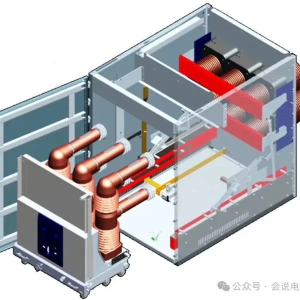 Read More
 -
Selection of internal arc test points for low-voltage switchgear
June 14, 2026According to the guidance of the national standard GB/T 18859-2016 (equivalent to IEC/TR61641), the ignition point for the interna Read More

Contact Us
Recommended Products
-
 Single Phase Oil Immersed Transformer 10KVA 15KVA 25KVA 37.5KVA Standard CompliantNegotiableMOQ: 2 Units
 -
Electrical Arc Furnace Transformers up to 120MVA - Certified for Steel Industry ApplicationsUS$ 8000 - 10000MOQ: 1 Unit
-
3-Phase Oil Type Transformer 5-Year Warranty With Load Test ReportUS$ 5428 - 5628MOQ: 1 Unit
-
Three Phase Oil Filled Transformer for Mining Operations Dust-Proof DesignUS$ 5428 - 5628MOQ: 1 Unit
-
HV Three Phase Oil Filled Transformer With ONAN Cooling 500kVA-2500kVAUS$ 5428 - 5628MOQ: 1 Unit
-
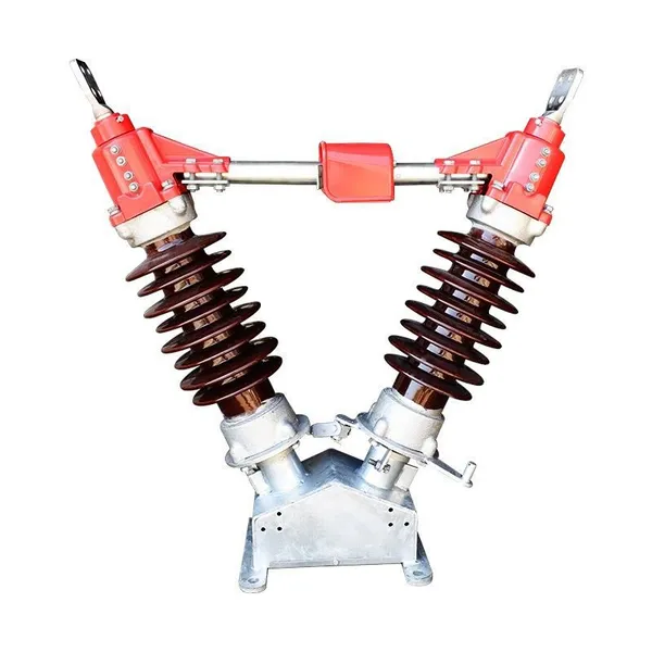
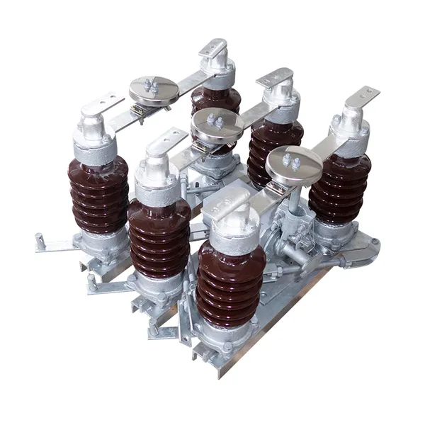
11/24/33KV High Voltage Isolation Switch With Mill Test ReportUS$ 800MOQ: 1 Unit
-
3-Pole Outdoor Isolation Switch With 5-Year Warranty and Compliance TestingUS$ 800MOQ: 1 Unit
-
YH5WZ 3KV-110KV Zinc Oxide Arrester for Power Station Outdoor High Voltage DistributionUS$ 21MOQ: 100 Units
-
Outdoor SF6 Load Break Switch LW30-72.5/1250A 24KV 630A 16KA Three PhaseUS$ 10000MOQ: 1 Unit
-
Input Line Reactor for CNC Machine Frequency Converters, 400V 60HzUS$ 65MOQ: 5 Units
-
Industrial Grade 35-220KV Oil-Immersed Current Transformer for SubstationsUS$ 480 - 500MOQ: 3 Units
-
LZZBJ9-20 Indoor 24kV High Voltage Cabinet Single-Phase 5-20 for Industrial Power SystemsUS$ 250MOQ: 3 Units
-
17.5 KV Full-enclosed Outdoor Epoxy Resin Casting and Double Pole Insulated Voltage TransformerUS$ 90 - 100MOQ: 1 Piece
-
Three Phase 30kVA SVC Voltage Regulator for Textile Manufacturing, Stable OutputUS$ 159MOQ: 10 Units
-
Amorphous Core 25kVA Transformer Compliant With IEC Standards for Power DistributionUS$ 1300 - 2900MOQ: 2 Units
-
CHINT NM8NDC-630 DC 1000V/Ui High-Voltage Circuit Breaker With 630A Frame CurrentUS$ 425 - 625MOQ: 100 Units
-
High Voltage Drop Out Fuse Cutout 33KV 27KV 24KV for Overhead LinesUS$ 35MOQ: 100 Units
-
TVR-10 KVA Automatic Voltage Stabilizer 220V ±0.5% Accuracy for Laboratory InstrumentsUS$ 103 - 123MOQ: 1 Unit
-
Universal 5000VA Voltage Transformer for International Appliances 110V-220VUS$ 102 - 107MOQ: 10 Units
-
500kV Three-Phase Oil-Immersed Auto Transformer 250MVA for Power GridsUS$ 800 - 9000MOQ: 1 Unit