
 Business License

Typical Primary Scheme and Layout of American Standard Low Voltage Switchgear
The UL1558/IEEE C37.20.1 standard is the standard for American standard low-voltage power switchgear. As a primary distribution switchgear, it requires high parameter performance, power system level protection, and high reliability requirements.
And a single solution needs to meet the requirements of complex system applications, with modular design of incoming lines, busbars, and outgoing lines, flexible combination of cabinets, meeting the requirements of different application scenarios, achieving the minimum number of switchgear and the highest economy.
A typical one-time outgoing line scheme is as follows: the horizontal busbar behind the cabinet is arranged in three positions: upper, middle, and lower. The horizontal busbar can be located in the upper, middle, or lower part of the cabinet, making the one-time scheme quite flexible.
Three sets of horizontal busbars can serve as backups for each other, operate independently, or run in parallel together. Each group of busbars can achieve a maximum current of 6000A and 150kA, and one group of busbars can carry all currents.
The high current incoming and outgoing lines and busbars, according to C37.20.1 standard, are installed inside a switchgear with a frame circuit breaker greater than 3200A. One switchgear can accommodate two 3200A frame circuit breakers arranged in a double-layer configuration.
As shown in the figure below, it can be two sets of incoming and outgoing lines directly to the central horizontal busbar behind the cabinet, or an upper incoming line with a lower 3200A frame circuit breaker as the busbar coupling for the central and lower busbars behind the cabinet. Alternatively, the 3200/4000A frame circuit breakers on both the upper and lower levels are connected to the upper and lower busbars of the busbar connection cabinet.
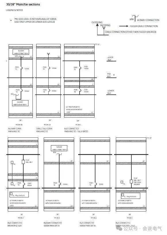
Similarly, for 4000/5000A single-layer incoming lines and bus tie circuit breakers, they can be directly connected to the upper and lower busbars behind the cabinet or connected to the busbars. It is also possible to install pull-out fuse cabinets for maintenance.
For 2000A and below current frame circuit breakers, one switchgear can install four units, with a standard design of four compartments from top to bottom.
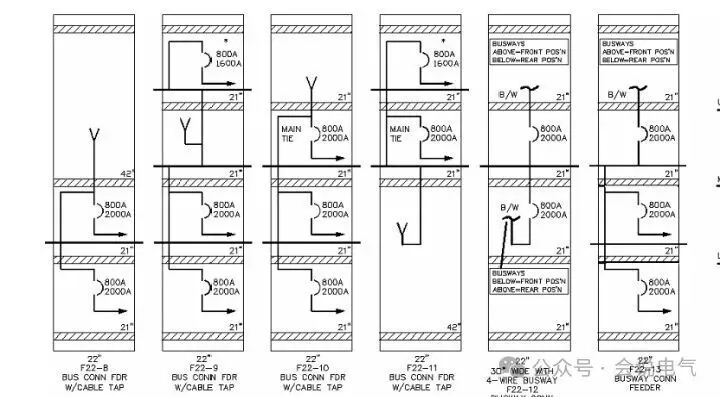
The arrangement of four layer circuit breakers will be more flexible and can also serve as a space for connecting bus bridges. The following single line diagram is only a small part of the configuration plan. Three busbars are respectively connected to the outgoing lines of the frame circuit breaker, or to the busbars between them, or to the incoming lines and the outgoing lines directly, etc.
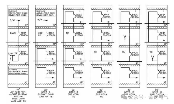
There are many combinations of solutions, with flexible one-time configuration to minimize the number of switchgear.
The C37.20.1 standard specifies the current carrying capacity reduction factor for two, three, and four withdrawable frame circuit breakers. For the four frame circuit breakers, the current carrying capacity is 50%, 60%, 75%, and 90%, respectively. If four 2000A frame circuit breakers are installed, the allowed current values are 1000A, 1200A, 1500A, and 1800A respectively, which means the total current=1000+1200+1500+1800=5500A.
Four frame circuit breakers require a large amount of space for connecting cables. The UL1558 low-voltage switchgear consists of four 2000A cabinets with a width of 22 inches (22 × 25.4=558.8mm), a depth of 70 inches (70 × 25.4=1778mm), and a height of 90 inches (90 × 25.4=2286mm).
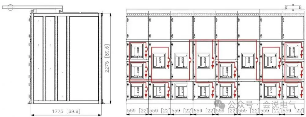
The four frame circuit breakers have separate compartments for incoming and outgoing cables, which generally require a depth of 25 inches, that is, 25 × 25.4=635mm depth space for cable connection. The 2000A adopts 6 500MCM copper core cables with a cable bending space of 330mm. Alternatively, 5 750MCM copper core cables with a minimum cable bending space of 534mm. Therefore, the bottom or top plate of the switchgear needs to reserve 96 cable entry and exit holes, which is the area for installing 96 M40 gland heads. Using four core cables can reduce the area, but there is still enough space for cable bending connections.
Recently Posted
-
Insulation issues of contact boxes for voltages of 24kV and above
September 8, 2026For medium voltage withdrawable circuit breaker switchgear, the contact box is a key insulation component. The main functions of t Read More
 -
The difference between Chinese made 40.5kV switchgear and North American 38kV switchgear
September 7, 2026Chinese made 40.5kV switchgear, with a power frequency withstand voltage of 95kV, lightning impulse withstand voltage of 185kV, an Read More
 -
Application of Low Voltage Switchgear Data Center Prefabricated Warehouse
September 7, 2026Prefabricated warehouses have become the preferred solution for applications such as data centers and new energy. High and low vol Read More
 -
The history of medium voltage switchgear
September 4, 2026Medium voltage circuit breakerIn 1895, GE developed the first oil circuit breaker, and in 1915, GE installed the first metal armor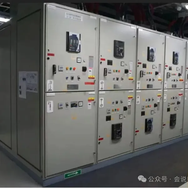 Read More

Contact Us
Recommended Products
-
 Single Phase Oil Immersed Transformer 10KVA 15KVA 25KVA 37.5KVA Standard CompliantNegotiableMOQ: 2 Units
 -
Electrical Arc Furnace Transformers up to 120MVA - Certified for Steel Industry ApplicationsUS$ 8000 - 10000MOQ: 1 Unit
-
3-Phase Oil Type Transformer 5-Year Warranty With Load Test ReportUS$ 5428 - 5628MOQ: 1 Unit
-
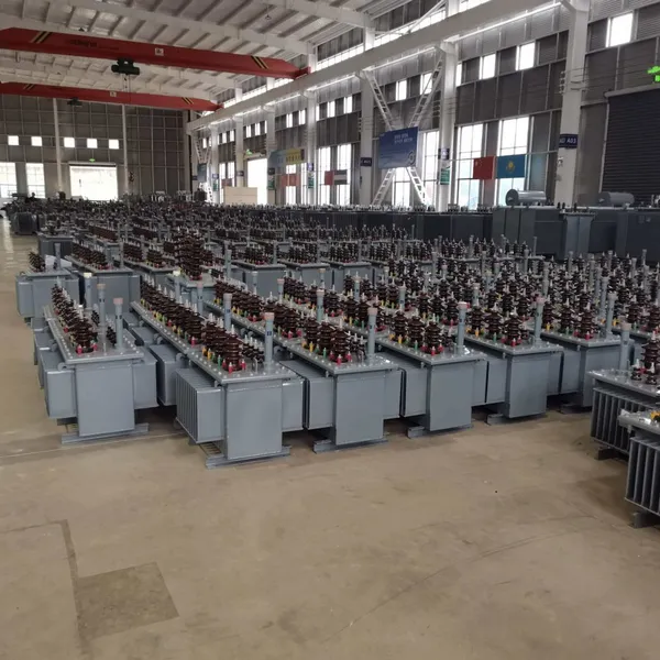
Three Phase Oil Filled Transformer for Mining Operations Dust-Proof DesignUS$ 5428 - 5628MOQ: 1 Unit
-
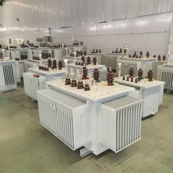
HV Three Phase Oil Filled Transformer With ONAN Cooling 500kVA-2500kVAUS$ 5428 - 5628MOQ: 1 Unit
-
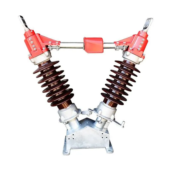
11/24/33KV High Voltage Isolation Switch With Mill Test ReportUS$ 800MOQ: 1 Unit
-
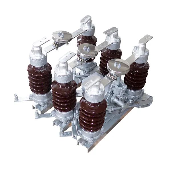
3-Pole Outdoor Isolation Switch With 5-Year Warranty and Compliance TestingUS$ 800MOQ: 1 Unit
-
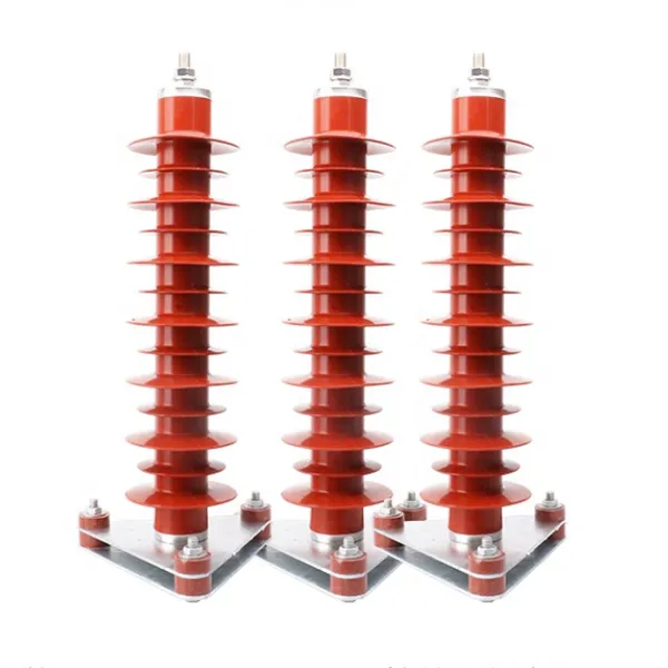
YH5WZ 3KV-110KV Zinc Oxide Arrester for Power Station Outdoor High Voltage DistributionUS$ 21MOQ: 100 Units
-
Outdoor SF6 Load Break Switch LW30-72.5/1250A 24KV 630A 16KA Three PhaseUS$ 10000MOQ: 1 Unit
-
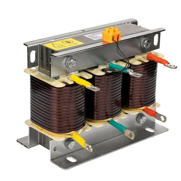
Input Line Reactor for CNC Machine Frequency Converters, 400V 60HzUS$ 65MOQ: 5 Units
-
Industrial Grade 35-220KV Oil-Immersed Current Transformer for SubstationsUS$ 480 - 500MOQ: 3 Units
-
LZZBJ9-20 Indoor 24kV High Voltage Cabinet Single-Phase 5-20 for Industrial Power SystemsUS$ 250MOQ: 3 Units
-
17.5 KV Full-enclosed Outdoor Epoxy Resin Casting and Double Pole Insulated Voltage TransformerUS$ 90 - 100MOQ: 1 Piece
-
Three Phase 30kVA SVC Voltage Regulator for Textile Manufacturing, Stable OutputUS$ 159MOQ: 10 Units
-
Amorphous Core 25kVA Transformer Compliant With IEC Standards for Power DistributionUS$ 1300 - 2900MOQ: 2 Units
-
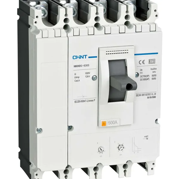
CHINT NM8NDC-630 DC 1000V/Ui High-Voltage Circuit Breaker With 630A Frame CurrentUS$ 425 - 625MOQ: 100 Units
-
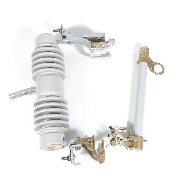
High Voltage Drop Out Fuse Cutout 33KV 27KV 24KV for Overhead LinesUS$ 35MOQ: 100 Units
-
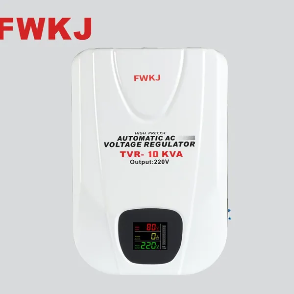
TVR-10 KVA Automatic Voltage Stabilizer 220V ±0.5% Accuracy for Laboratory InstrumentsUS$ 103 - 123MOQ: 1 Unit
-
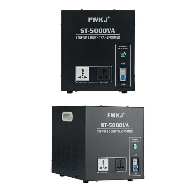
Universal 5000VA Voltage Transformer for International Appliances 110V-220VUS$ 102 - 107MOQ: 10 Units
-
500kV Three-Phase Oil-Immersed Auto Transformer 250MVA for Power GridsUS$ 800 - 9000MOQ: 1 Unit