
 Business License

Insulation issues of contact boxes for voltages of 24kV and above
For medium voltage withdrawable circuit breaker switchgear, the contact box is a key insulation component. The main functions of the contact box are to support the static contacts, establish electrical connections between compartments, and provide electrical insulation between the static contacts of the circuit breaker and the metal mounting plate.
Especially for high current switchgear, the contact arm diameter of the circuit breaker is large, the distance from the inner wall of the contact box is small, and the outer side of the contact box is directly connected to the installation board for grounding. If the inner diameter of the contact box is 214mm and the contact arm diameter of the circuit breaker is 100mm, the distance from the inner wall to the contact arm is 57mm, the wall thickness of the contact box is 15mm, and the distance from the outer side of the contact box to the installation plate is 5mm.
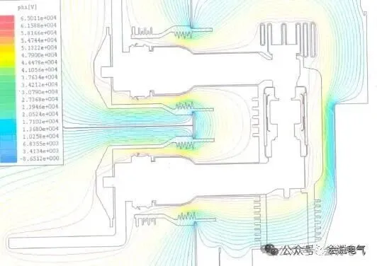
For 12kV and a power frequency withstand voltage of 42kV, calculated based on the dielectric constant of epoxy resin as 4, the voltage division between air (5 * 4)/(57 * 4+15 * 1+5 * 4) * 42=3.19kV.
For coaxial rings and parallel surfaces, the electric field tends to be uniform, and the electric field strength tends to be evenly distributed, that is, 3.19/5=0.638kV/mm.
However, the installation situation on the outside of the contact box is not like this, but rather a sharp steel plate with a very small curvature radius at the tip. In order to maintain the equipotential state of the conductor surface, a large amount of charges will accumulate at the tip, resulting in a much higher surface density of charges at the tip than on a flat or smooth surface, thus generating a strong local electric field. That is to say, the electric field is concentrated on the surface of the steel plate opening, rather than uniformly distributed. The electric field lines are dense and radiating at the tip, and as the distance from the tip increases, the electric field strength rapidly decays, gradually approaching the macroscopic background electric field.
The electric field strength is roughly inversely proportional to the square of the distance, that is, the farther away from the tip, the faster the decrease in electric field strength. 3.19/4=0.7975,3.19/9=0.3544,3.19/16=0.1993,3.19/25=0.1276,3.19-0.1276-0.1993-0.3544-0.7975=1.71kV
When the electric field is concentrated within a distance of 5mm, the air near the tip ionizes and discharges (breakdown effect). When the local electric field strength at the tip exceeds the critical breakdown field strength of air (about 3 × 10 ⁶ V/m), it will vigorously "pull" air molecules, causing them to ionize (i.e. electrons are stripped off, forming free electrons and positive ions). These charged particles generated by ionization undergo avalanche collision ionization under the action of a strong electric field, forming a conductive channel through which charges leak from the tip into the air, forming visible discharges such as corona discharge or spark discharge.
For 24kV and a power frequency withstand voltage of 65kV, calculated based on the dielectric constant of epoxy resin as 4, the voltage division between air (5 * 4)/(57 * 4+15 * 1+5 * 4) * 65=4.94kV.
4.94/4=1.235,4.94/9=0.549,4.94/16=0.31,4.94/25=0.197,4.94-1.235-0.549-0.31-0.197=2.649kV Close to the critical breakdown field strength of air, it will discharge.
In fact, the voltage distribution will not be as evenly distributed as calculated earlier, but the electric field near the installation plate will be higher, which will actually cause discharge.
The above is the simplest calculation, but in reality, the distribution of electric fields is much more complex. Therefore, products with internal and external voltage equalization shielding should be selected for 24kV and above through wall bushings, contact boxes, etc., in order to evenly distribute the electric field, distribute more insulation voltage inside the solid insulation layer, maximize the insulation performance of solid materials, reduce the strength of the air electric field, and ensure long-term stable operation.
Recently Posted
-
Typical Primary Scheme and Layout of American Standard Low Voltage Switchgear
September 7, 2026The UL1558/IEEE C37.20.1 standard is the standard for American standard low-voltage power switchgear. As a primary distribution sw Read More
 -
The difference between Chinese made 40.5kV switchgear and North American 38kV switchgear
September 7, 2026Chinese made 40.5kV switchgear, with a power frequency withstand voltage of 95kV, lightning impulse withstand voltage of 185kV, an Read More
 -
Application of Low Voltage Switchgear Data Center Prefabricated Warehouse
September 7, 2026Prefabricated warehouses have become the preferred solution for applications such as data centers and new energy. High and low vol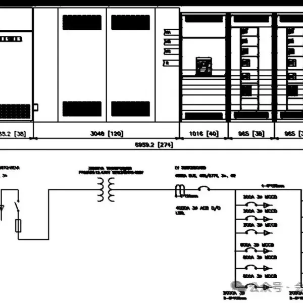 Read More
 -
The history of medium voltage switchgear
September 4, 2026Medium voltage circuit breakerIn 1895, GE developed the first oil circuit breaker, and in 1915, GE installed the first metal armor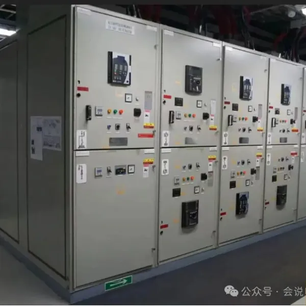 Read More

Contact Us
Recommended Products
-
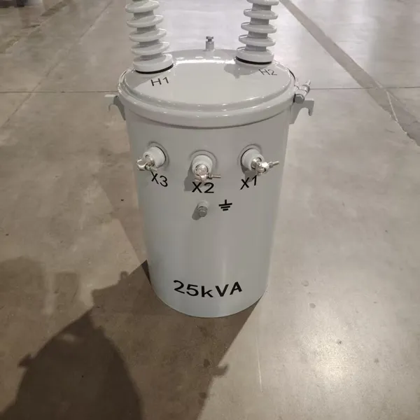
 Single Phase Oil Immersed Transformer 10KVA 15KVA 25KVA 37.5KVA Standard CompliantNegotiableMOQ: 2 Units
 -
Electrical Arc Furnace Transformers up to 120MVA - Certified for Steel Industry ApplicationsUS$ 8000 - 10000MOQ: 1 Unit
-
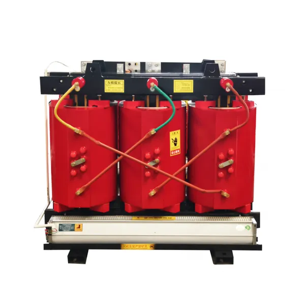
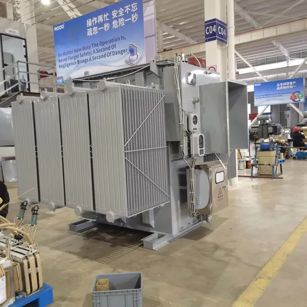
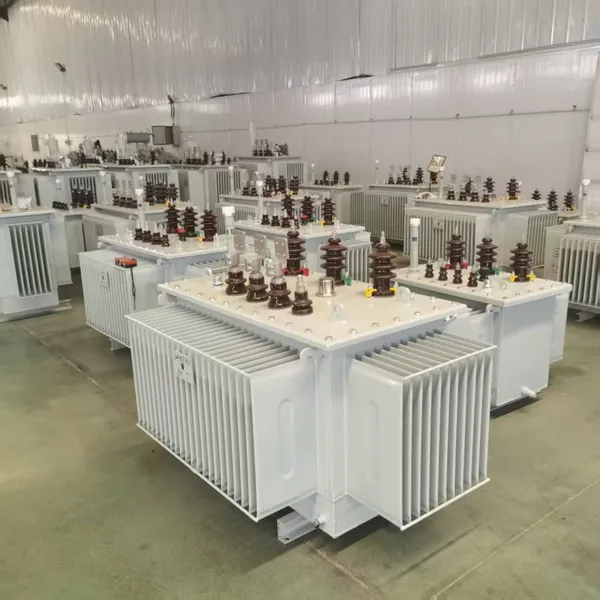
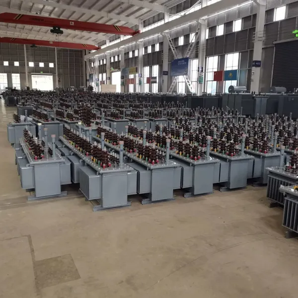
3-Phase Oil Type Transformer 5-Year Warranty With Load Test ReportUS$ 5428 - 5628MOQ: 1 Unit
-
Three Phase Oil Filled Transformer for Mining Operations Dust-Proof DesignUS$ 5428 - 5628MOQ: 1 Unit
-
HV Three Phase Oil Filled Transformer With ONAN Cooling 500kVA-2500kVAUS$ 5428 - 5628MOQ: 1 Unit
-
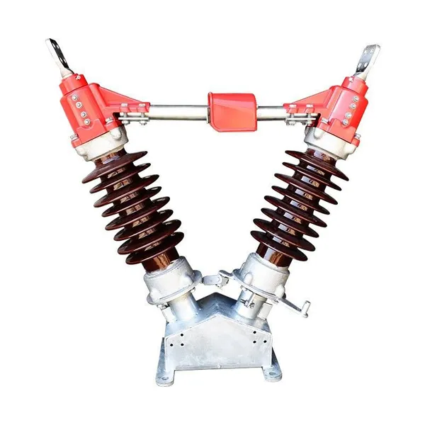
11/24/33KV High Voltage Isolation Switch With Mill Test ReportUS$ 800MOQ: 1 Unit
-
3-Pole Outdoor Isolation Switch With 5-Year Warranty and Compliance TestingUS$ 800MOQ: 1 Unit
-
YH5WZ 3KV-110KV Zinc Oxide Arrester for Power Station Outdoor High Voltage DistributionUS$ 21MOQ: 100 Units
-
Outdoor SF6 Load Break Switch LW30-72.5/1250A 24KV 630A 16KA Three PhaseUS$ 10000MOQ: 1 Unit
-
Input Line Reactor for CNC Machine Frequency Converters, 400V 60HzUS$ 65MOQ: 5 Units
-
Industrial Grade 35-220KV Oil-Immersed Current Transformer for SubstationsUS$ 480 - 500MOQ: 3 Units
-
LZZBJ9-20 Indoor 24kV High Voltage Cabinet Single-Phase 5-20 for Industrial Power SystemsUS$ 250MOQ: 3 Units
-
17.5 KV Full-enclosed Outdoor Epoxy Resin Casting and Double Pole Insulated Voltage TransformerUS$ 90 - 100MOQ: 1 Piece
-
Three Phase 30kVA SVC Voltage Regulator for Textile Manufacturing, Stable OutputUS$ 159MOQ: 10 Units
-
Amorphous Core 25kVA Transformer Compliant With IEC Standards for Power DistributionUS$ 1300 - 2900MOQ: 2 Units
-
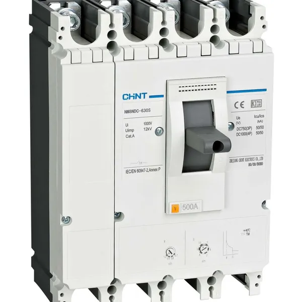
CHINT NM8NDC-630 DC 1000V/Ui High-Voltage Circuit Breaker With 630A Frame CurrentUS$ 425 - 625MOQ: 100 Units
-
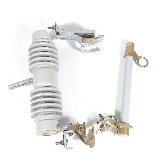
High Voltage Drop Out Fuse Cutout 33KV 27KV 24KV for Overhead LinesUS$ 35MOQ: 100 Units
-
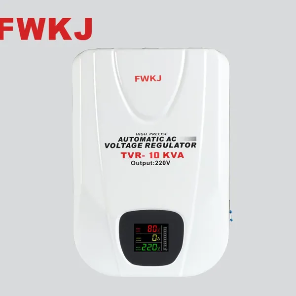
TVR-10 KVA Automatic Voltage Stabilizer 220V ±0.5% Accuracy for Laboratory InstrumentsUS$ 103 - 123MOQ: 1 Unit
-
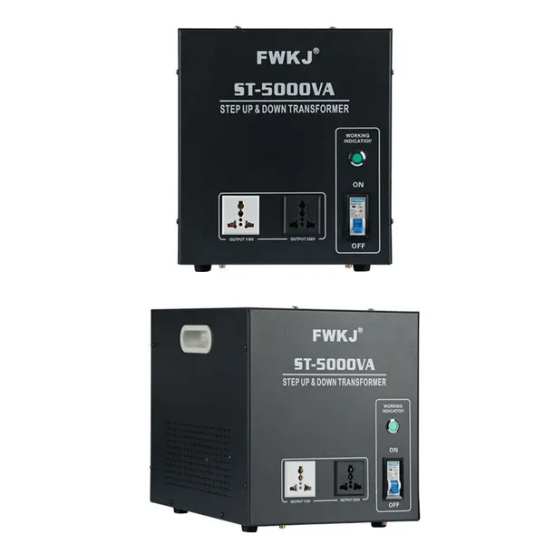
Universal 5000VA Voltage Transformer for International Appliances 110V-220VUS$ 102 - 107MOQ: 10 Units
-
500kV Three-Phase Oil-Immersed Auto Transformer 250MVA for Power GridsUS$ 800 - 9000MOQ: 1 Unit