
 Business License

What Is a Distribution Transformer and How Does It Work?
A project manager once described watching a whole neighborhood go dark because a single pole-mounted unit failed on a hot afternoon. The fault was traced back to a distribution transformer that had been overloaded for months, running roughly 20% above its nameplate rating before its insulation finally broke down.
If you buy or specify electrical equipment, that kind of failure is expensive and entirely avoidable. The good news is that the device behind most of these incidents is well understood, and getting the basics right removes most of the risk.
This guide explains what a distribution transformer is, where it sits in the grid, how it steps voltage down, and what to look for when you select one.
1. A Distribution Transformer Is the Last Step Before Your Outlet
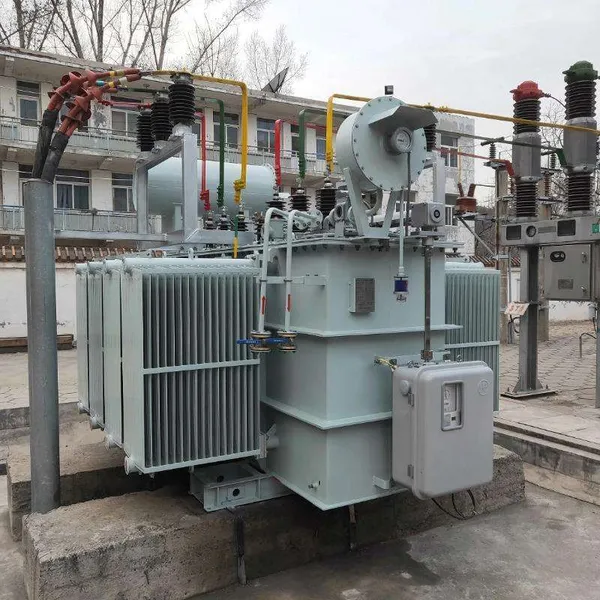
A distribution transformer is the final voltage-reduction stage between the high-voltage transmission network and the low-voltage power that actually runs your building. It takes medium voltage from a feeder line and steps it down to a level that equipment can safely use, typically 400 V three-phase or 230 V single-phase.
Almost every transformer you see on a utility pole, in a ground-mounted enclosure, or inside a commercial building falls into this category. They are the most numerous type of transformer in service, and they run continuously for decades with very little attention.
In practice, a distribution transformer is defined less by its construction and more by its job. The same basic machine can be oil-immersed or dry-type, pole-mounted or pad-mounted, but its role is always to deliver usable voltage to the point of consumption.
Because they are so widespread, distribution transformers are also heavily standardized. International standards such as IEC 60076 define their ratings, testing, and performance requirements, which makes cross-border sourcing far more predictable than it would otherwise be.
2. Where Distribution Transformers Sit in the Power Grid
Electricity leaves a power plant at high voltage, often 110 kV or more, because high voltage minimizes current and therefore reduces line losses over long distances. Transmission lines carry this power to substations, where large power transformers step it down to medium voltage.
From there, distribution feeders run through neighborhoods and industrial parks at voltages such as 11 kV, 13.8 kV, or 33 kV. A distribution transformer taps into one of these feeders and drops the voltage one final time, delivering 400/230 V to a small group of homes or a single factory.
This structure matters for buyers because the input voltage of the transformer must match the local feeder, and the output voltage must match the local utilization standard. Getting either one wrong means the unit cannot be connected at all.
Most distribution transformers are three-phase, but single-phase units remain common in residential areas where each home taps a single phase of a three-phase feeder. The phase configuration must be stated at order time, because it changes the winding layout and the bushing arrangement.
3. Core Components of a Distribution Transformer
Although the design looks simple from the outside, a distribution transformer contains several precision-built components. Understanding them makes it much easier to read a specification sheet and ask the right questions of a supplier.
The magnetic core is made of thin silicon-steel laminations stacked together, a design that cuts eddy-current losses to a fraction of what a solid core would produce. Around the core sit two windings: a primary winding connected to the high-voltage side and a secondary winding on the low-voltage side.
A key quality factor is the grade of silicon steel in the core, because better grades reduce no-load loss at the cost of a higher material price. Reputable manufacturers balance these two, and the choice is often visible in the quoted no-load loss figure rather than in any physical feature.
The windings are wrapped in insulating material and, in an oil-immersed unit, submerged in mineral oil that both insulates and carries heat away. A tank, a conservator or pressure system, bushings, and a tap changer complete the assembly.
4. How a Distribution Transformer Steps Down Voltage
The voltage transformation follows a simple ratio rule. If the primary winding has 2,000 turns and the secondary has 400 turns, an 11 kV input becomes roughly 2.2 kV on the output. Choosing the right turn ratio is what sets the output voltage to exactly the level the customer needs.
The real engineering challenge is not the ratio itself but managing the magnetic flux and the losses that come with it. Every transformer draws a small magnetizing current even at no load, and this is why a unit that is switched on but doing nothing still consumes a little power.
Under load, the secondary current creates its own magnetic field that opposes the primary field, and the primary automatically draws more current to maintain the flux balance. This self-regulating behavior is what allows a transformer to serve a varying load without any moving parts.
A tap changer provides a small range of adjustment, usually plus or minus 5% in a few steps, to correct for voltage drop along long feeders. Most distribution transformers use an off-circuit tap changer that is adjusted only when the unit is de-energized, which keeps the design simple and the cost low.
5. Common Ratings and Configurations
Distribution transformers are specified by a handful of key parameters, and the values vary by region. The table below summarizes the most common ranges a buyer will encounter when sourcing for international projects.
| Parameter | Typical Range | Notes |
|---|---|---|
| Rated power | 50 kVA to 2,500 kVA | Larger units are usually classed as power transformers |
| Primary voltage | 6 kV, 10 kV, 11 kV, 13.8 kV, 33 kV | Matches the local medium-voltage feeder |
| Secondary voltage | 400/230 V, 415/240 V, 480/277 V | Matches the utilization standard |
| Frequency | 50 Hz or 60 Hz | Never interchangeable without derating |
| Cooling | ONAN (oil), AN/AF (dry) | Determines load capacity and enclosure needs |
These parameters are the first thing a reputable manufacturer will confirm, because every other design decision flows from them. A 60 Hz unit run on a 50 Hz system, for example, will overheat and fail early, even though it looks identical to the correct model.
6. Types of Distribution Transformers
The two broad families are oil-immersed and dry-type. Oil-immersed units cool the windings with mineral oil and are the workhorses of outdoor and utility use, offering high overload tolerance at a lower first cost.
Dry-type transformers use air or cast-resin insulation instead of liquid, which removes the fire and leak concerns that come with oil. They are favored indoors, in hospitals, high-rise buildings, and anywhere an oil spill would be unacceptable.
Within these families, buyers also choose between pole-mounted, pad-mounted, and substation-style designs. The mounting style affects everything from the enclosure to the cable entry points, so it should be confirmed early in the project.
Dry-type units are further classified by their insulation class, with Class F and Class H being common, indicating maximum winding temperatures of 155°C and 180°C respectively. Cast-resin windings add mechanical strength and moisture resistance, which is why they appear in harsh or humid indoor environments.
7. Efficiency and Losses: What They Mean for Your Power Bill
Modern distribution transformers are efficient machines, typically operating at 97% to 99% efficiency at full load. That small remaining fraction still matters, because it runs 24 hours a day, every day, for the life of the unit.
Losses split into two parts. No-load loss, also called iron or core loss, is constant and flows through the core whenever the transformer is energized. Load loss, or copper loss, rises with the square of the current and dominates when the unit runs near capacity.
For a buyer, the efficiency choice is often an economic one. A higher-efficiency unit costs more up front but can recover that premium through lower energy losses within a few years, especially in regions with expensive electricity.
A customer we worked with replaced an aging unit running at roughly 96.5% efficiency with a modern model above 99%. The higher purchase price was recovered in about three years through lower no-load losses alone, because the site operated around the clock on expensive grid power.
8. Sizing a Distribution Transformer for Your Load
Choosing the right size means matching the transformer to the actual and projected load, not simply picking the biggest affordable unit. A transformer that is too large runs at light load and wastes energy through its constant core loss, while one that is too small overheats and shortens its life.
The table below offers a rough starting point for selecting rated power based on the connected load profile.
| Connected Load | Suggested Rating | Loading Consideration |
|---|---|---|
| Up to 40 kW continuous | 50 kVA | Light commercial, small shops |
| 80–120 kW mixed | 160 kVA | Typical small factory or building |
| 300–400 kW industrial | 500–630 kVA | Allow headroom for motor starting |
| 1,000 kW+ with motors | 1,600–2,000 kVA | Confirm inrush and harmonic load first |
These figures are guidelines, not rules. Motor starting currents, harmonic loads, and future expansion plans all shift the answer, which is why a manufacturer should review the full load profile before quoting.
Many engineers size for a loading of roughly 70% to 80% at peak, which balances the constant core loss against the variable load loss and leaves headroom for a hot afternoon or a future machine. Oversizing beyond this comfort zone rarely pays, because the extra core loss runs continuously whether or not the capacity is used.
9. Choosing a Reliable Manufacturer
The difference between a well-built distribution transformer and a poor one is rarely visible on the outside. It shows up in the quality of the core steel, the precision of the winding, and the discipline of the factory test program.
This is where working with an experienced supplier pays off. Jinhua Dika Electrical Equipment Co., Ltd. manufactures transformers and complete switchgear from its facility in Jinhua, Zhejiang Province, and tests every unit against the relevant IEC standards before dispatch.
Dika Electrical Equipment has built its export business on confirming each specification twice: once at the quoting stage and again at the pre-shipment inspection. For a buyer importing equipment across borders, that second confirmation is often what prevents an expensive mismatch on arrival.
Our team at Jinhua Dika Electrical Equipment performs a full routine test on every transformer that leaves the factory, covering winding resistance, voltage ratio, no-load loss, and applied voltage. Buyers receive the test report with the unit, so the numbers can be verified independently before the equipment is energized.
10. FAQ
10.1 What is the difference between a distribution transformer and a power transformer?
A distribution transformer steps medium voltage down to the utilization level and usually runs at 50 kVA to 2,500 kVA. A power transformer operates at higher voltages and larger ratings, typically in transmission substations. The two are built on the same physics, but a distribution transformer is designed for continuous duty at part load and near the end user, while a power transformer handles bulk transfer across the grid.
10.2 How long does a distribution transformer last?
An oil-immersed distribution transformer typically lasts 25 to 40 years when it is not overloaded and receives occasional maintenance such as oil sampling. Dry-type units generally reach 20 to 30 years indoors. The biggest threats to lifespan are sustained overload, poor ventilation, and moisture ingress, all of which degrade insulation faster than normal aging would.
10.3 Can a 50 Hz transformer run on 60 Hz?
Running a 50 Hz transformer on 60 Hz is not automatically safe. The higher frequency reduces the required flux for a given voltage, which can actually lower core loss, but the output voltage and cooling behavior change, and the unit may no longer meet its rating. Running a 60 Hz unit on 50 Hz is worse and will typically cause overheating. Frequency must be specified correctly at the order stage.
10.4 What does ONAN mean on a transformer nameplate?
ONAN stands for Oil Natural Air Natural, a cooling code that describes how the transformer sheds heat. The oil circulates by natural convection without a pump, and the tank surface is cooled by natural air movement without a fan. It is the most common cooling method for distribution transformers and indicates a simple, low-maintenance design with no auxiliary cooling equipment.
Recently Posted
-
Transformer Factory Tests: Routine, Type and Special Tests Explained
August 28, 2026An importer once accepted a transformer shipment without reading the test report, only to find the unit failed on site because its Read More
 -
UL891 distribution panel
August 28, 2026Switchgear and separately separated distribution panels require a rear channel for connecting incoming and outgoing feeder cables.
Read More -
Oil-Immersed Transformers for Solar PV Power Plants
August 27, 2026A solar developer once watched a new plant lose several weeks of generation because the transformer feeding the grid connection fa Read More
 -
Dry-Type vs Oil-Immersed Transformer: How to Choose
August 26, 2026A facilities engineer once had to shut down a hospital wing because the transformer serving it leaked oil onto the floor below. Th Read More

Contact Us
Recommended Products
-
 Single Phase Oil Immersed Transformer 10KVA 15KVA 25KVA 37.5KVA Standard CompliantNegotiableMOQ: 2 Units
 -
Electrical Arc Furnace Transformers up to 120MVA - Certified for Steel Industry ApplicationsUS$ 8000 - 10000MOQ: 1 Unit
-
3-Phase Oil Type Transformer 5-Year Warranty With Load Test ReportUS$ 5428 - 5628MOQ: 1 Unit
-
Three Phase Oil Filled Transformer for Mining Operations Dust-Proof DesignUS$ 5428 - 5628MOQ: 1 Unit
-
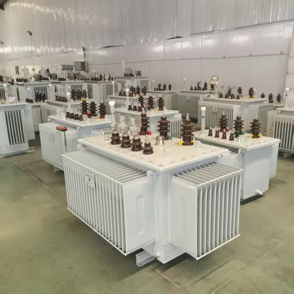
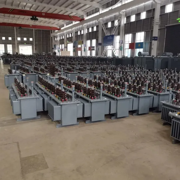
HV Three Phase Oil Filled Transformer With ONAN Cooling 500kVA-2500kVAUS$ 5428 - 5628MOQ: 1 Unit
-
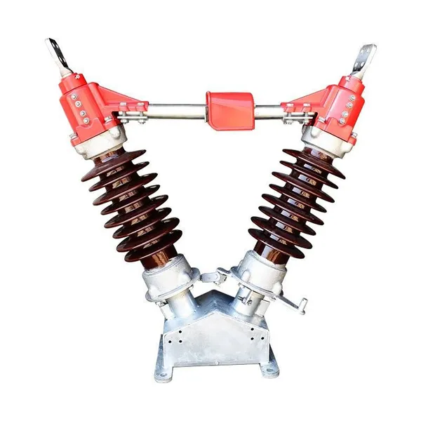
11/24/33KV High Voltage Isolation Switch With Mill Test ReportUS$ 800MOQ: 1 Unit
-
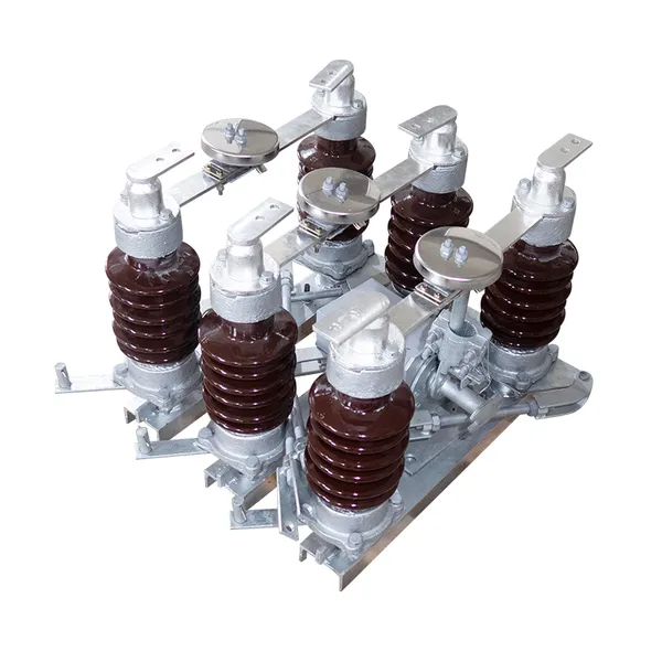
3-Pole Outdoor Isolation Switch With 5-Year Warranty and Compliance TestingUS$ 800MOQ: 1 Unit
-
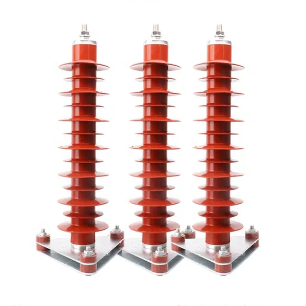
YH5WZ 3KV-110KV Zinc Oxide Arrester for Power Station Outdoor High Voltage DistributionUS$ 21MOQ: 100 Units
-
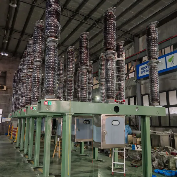
Outdoor SF6 Load Break Switch LW30-72.5/1250A 24KV 630A 16KA Three PhaseUS$ 10000MOQ: 1 Unit
-
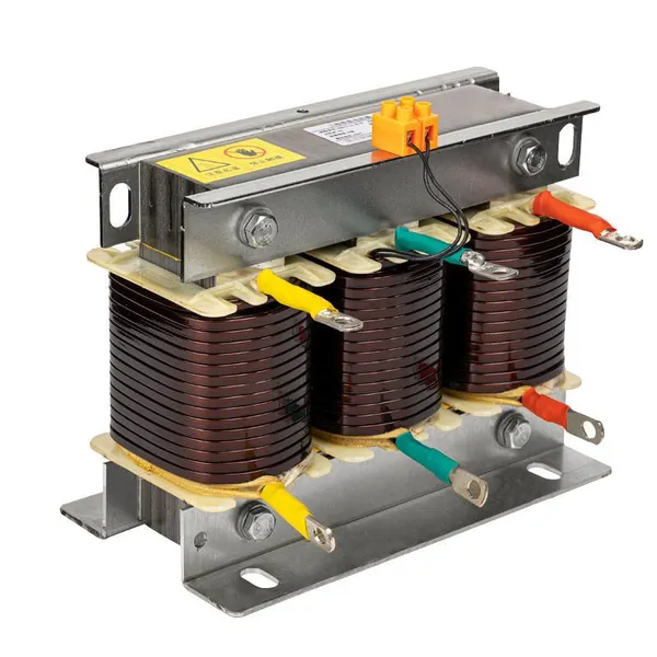
Input Line Reactor for CNC Machine Frequency Converters, 400V 60HzUS$ 65MOQ: 5 Units
-
Industrial Grade 35-220KV Oil-Immersed Current Transformer for SubstationsUS$ 480 - 500MOQ: 3 Units
-
LZZBJ9-20 Indoor 24kV High Voltage Cabinet Single-Phase 5-20 for Industrial Power SystemsUS$ 250MOQ: 3 Units
-
17.5 KV Full-enclosed Outdoor Epoxy Resin Casting and Double Pole Insulated Voltage TransformerUS$ 90 - 100MOQ: 1 Piece
-
Three Phase 30kVA SVC Voltage Regulator for Textile Manufacturing, Stable OutputUS$ 159MOQ: 10 Units
-
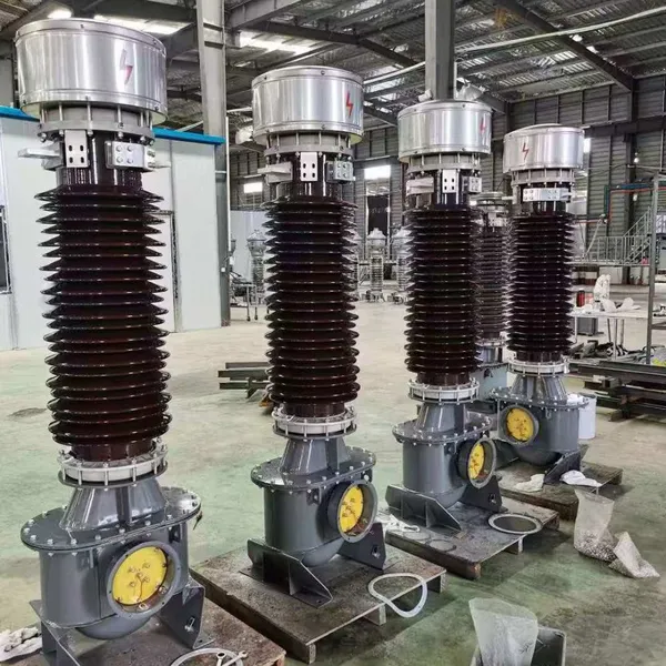
Amorphous Core 25kVA Transformer Compliant With IEC Standards for Power DistributionUS$ 1300 - 2900MOQ: 2 Units
-
CHINT NM8NDC-630 DC 1000V/Ui High-Voltage Circuit Breaker With 630A Frame CurrentUS$ 425 - 625MOQ: 100 Units
-
High Voltage Drop Out Fuse Cutout 33KV 27KV 24KV for Overhead LinesUS$ 35MOQ: 100 Units
-
TVR-10 KVA Automatic Voltage Stabilizer 220V ±0.5% Accuracy for Laboratory InstrumentsUS$ 103 - 123MOQ: 1 Unit
-
Universal 5000VA Voltage Transformer for International Appliances 110V-220VUS$ 102 - 107MOQ: 10 Units
-
500kV Three-Phase Oil-Immersed Auto Transformer 250MVA for Power GridsUS$ 800 - 9000MOQ: 1 Unit