
The transformer in the high-voltage cabinet burned during operation. What is the reason?
1. Overvoltage Phenomena
Overvoltage is the leading culprit behind PT failures, encompassing two main scenarios:
Ferromagnetic Resonance: Prevalent in ungrounded or under-10kV systems, ferromagnetic resonance occurs when system disturbances (e.g., single-phase grounding, breaker misoperation) trigger abnormal oscillations between PT inductance and line capacitance. This generates overvoltages several times the rated value, damaging windings and insulation . A chemical plant’s 10kV PT explosion was traced to resonant overvoltage caused by incorrect open-delta wiring, which amplified voltage fluctuations .
Lightning and Transient Overvoltages: Direct or induced lightning strikes inject massive surge voltages into PTs. Since most PTs are grounded via secondary windings, they lack sufficient insulation to withstand such pulses . Similarly, capacitor switching induces transient overvoltages that exceed PT dielectric limits, leading to insulation breakdown .
2. Wiring Errors and Secondary Circuit Faults
Incorrect wiring accounts for a significant portion of PT explosions, often overlooked during installation and maintenance:
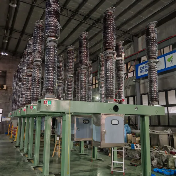
Secondary Short Circuits: Misrouted secondary windings (e.g., phase-to-phase or phase-to-ground shorts) create excessive current, overheating windings and igniting insulation. A 110kV GIS substation explosion occurred 43 seconds after commissioning when C-phase auxiliary windings were incorrectly connected, causing a short circuit that melted insulation and triggered arc-induced pressure buildup .
Open-Delta Misconfiguration: Swapped L and N terminals in open-delta windings (used for insulation monitoring) create virtual short circuits. This led to repeated PT burnout and a catastrophic explosion in a urea plant’s 10kV switchgear .
Unused Winding Neglect: Unconnected auxiliary windings, if left unterminated, can act as resonant cavities, amplifying voltage stresses .
3. Equipment Quality and Insulation Degradation
Manufacturing defects and aging significantly increase explosion risks:
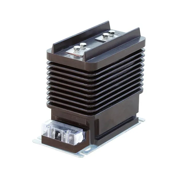
Insulation Flaws: Impurities, air bubbles, or poor epoxy casting in PT windings reduce dielectric strength, causing partial discharges and eventual breakdown . A 10kV security segment PT explosion was attributed to insulation degradation in the primary winding, leading to phase-to-phase short circuits .
Inadequate Insulation Class: Semi-insulated PTs are prone to failure if ground resistance exceeds limits. Upgrading to fully insulated PTs resolves recurrent fuse blowing and explosion risks .
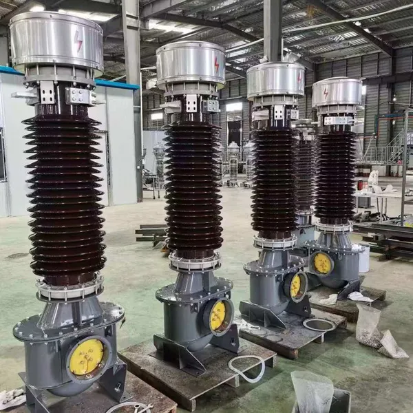
Aging and Wear: Long-term operation at elevated temperatures or humidity accelerates insulation aging. A 35kV thermal power plant PT explosion was linked to 15 years of service without insulation renewal, leading to progressive breakdown .
4. System Disturbances and External Factors
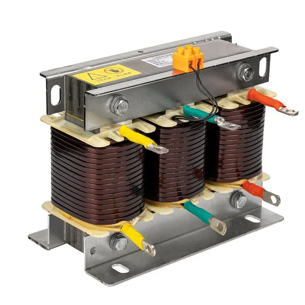
Inrush Current Impact: Capacitor bank switching generates inrush currents up to 50x the rated value, mechanical stressing PT windings and damaging insulation . Installing surge-limiting reactors or synchronous switches mitigates this risk.
Harmonic Resonance: Nonlinear loads (e.g., variable frequency drives) introduce harmonics that drive PT cores into deep saturation, increasing excitation current and heating . This creates a feedback loop that escalates to insulation failure.
Prevention and Mitigation Strategies
To minimize PT explosions, implement these proactive measures:
Install Harmonic Suppression Devices: Add open-delta resonance dampers (resistors or electronic suppressors) to dissipate resonant energy . For primary-side protection, use nonlinear zinc oxide neutral point resistors .
Rigorous Wiring Verification: Conduct comprehensive secondary circuit checks, including continuity tests and polarity verification. Label terminals clearly and follow manufacturer diagrams .
Quality Assurance: Select PTs with certified insulation systems and conduct pre-installation dielectric tests. Avoid semi-insulated PTs in unstable grounding environments .
Condition Monitoring: Deploy infrared thermography to detect abnormal heating and partial discharges. Integrate fault recorders to analyze voltage/current waveforms for resonant signatures .
Surge Protection: Install metal-oxide surge arresters (MOSAs) on PT primary sides to divert lightning and transient surges .
Conclusion
PT explosions in operating switchgears stem from interconnected factors: overvoltage events, wiring errors, equipment defects, and system disturbances. By understanding these mechanisms and implementing targeted prevention strategies—such as resonance suppression, strict wiring protocols, and proactive monitoring—facilities can safeguard personnel, minimize downtime, and ensure grid reliability. Regular maintenance and adherence to industry standards are non-negotiable to mitigate these high-stakes risks.
Recently Posted
-
System scheme and primary structure of American standard medium and low voltage switchgear
July 1, 2026The system scheme for power distribution comprehensively reflects the direction of power flow, current distribution, short-circuit Read More
 -
IEC 17.5kV switchgear Guzhou Weng will speak on electrical June 28, 2026 05:03 2 people
June 30, 202617.5kV is the IEC standard voltage level, applied in power systems with voltages of 13.2/13.8/15kV. IEC 17.5kV metal enclosed swit Read More
 -
Design points of customized switchgear
June 30, 2026With the increasing demand for new energy and data centers, in addition to standardized products, there is a need for a large numb Read More
 -
Marine low-voltage switchgear
June 30, 2026Marine low-voltage switchgear needs to meet the special requirements of ship application systems, environments, etc., and develop Read More

Contact Us
Recommended Products
-
 Single Phase Oil Immersed Transformer 10KVA 15KVA 25KVA 37.5KVA Standard CompliantNegotiableMOQ: 2 Units
 -
Electrical Arc Furnace Transformers up to 120MVA - Certified for Steel Industry ApplicationsUS$ 8000 - 10000MOQ: 1 Unit
-
3-Phase Oil Type Transformer 5-Year Warranty With Load Test ReportUS$ 5428 - 5628MOQ: 1 Unit
-
Three Phase Oil Filled Transformer for Mining Operations Dust-Proof DesignUS$ 5428 - 5628MOQ: 1 Unit
-
HV Three Phase Oil Filled Transformer With ONAN Cooling 500kVA-2500kVAUS$ 5428 - 5628MOQ: 1 Unit
-
11/24/33KV High Voltage Isolation Switch With Mill Test ReportUS$ 800MOQ: 1 Unit
-
3-Pole Outdoor Isolation Switch With 5-Year Warranty and Compliance TestingUS$ 800MOQ: 1 Unit
-
YH5WZ 3KV-110KV Zinc Oxide Arrester for Power Station Outdoor High Voltage DistributionUS$ 21MOQ: 100 Units
-
Outdoor SF6 Load Break Switch LW30-72.5/1250A 24KV 630A 16KA Three PhaseUS$ 10000MOQ: 1 Unit
-
Input Line Reactor for CNC Machine Frequency Converters, 400V 60HzUS$ 65MOQ: 5 Units
-
Industrial Grade 35-220KV Oil-Immersed Current Transformer for SubstationsUS$ 480 - 500MOQ: 3 Units
-
LZZBJ9-20 Indoor 24kV High Voltage Cabinet Single-Phase 5-20 for Industrial Power SystemsUS$ 250MOQ: 3 Units
-
17.5 KV Full-enclosed Outdoor Epoxy Resin Casting and Double Pole Insulated Voltage TransformerUS$ 90 - 100MOQ: 1 Piece
-
Three Phase 30kVA SVC Voltage Regulator for Textile Manufacturing, Stable OutputUS$ 159MOQ: 10 Units
-
Amorphous Core 25kVA Transformer Compliant With IEC Standards for Power DistributionUS$ 1300 - 2900MOQ: 2 Units
-
CHINT NM8NDC-630 DC 1000V/Ui High-Voltage Circuit Breaker With 630A Frame CurrentUS$ 425 - 625MOQ: 100 Units
-
High Voltage Drop Out Fuse Cutout 33KV 27KV 24KV for Overhead LinesUS$ 35MOQ: 100 Units
-
TVR-10 KVA Automatic Voltage Stabilizer 220V ±0.5% Accuracy for Laboratory InstrumentsUS$ 103 - 123MOQ: 1 Unit
-
Universal 5000VA Voltage Transformer for International Appliances 110V-220VUS$ 102 - 107MOQ: 10 Units
-
500kV Three-Phase Oil-Immersed Auto Transformer 250MVA for Power GridsUS$ 800 - 9000MOQ: 1 Unit